Article Content
Introduction to the JDZW-35 Current Transformer
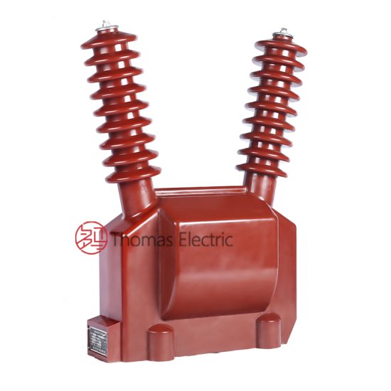
The JDZW-35 is a high-precision, cast-resin insulated current transformer (CT) engineered for critical metering and protection functions in medium-voltage (MV) power systems operating at nominal system voltages up to 11 kV. Unlike legacy oil-immersed or gas-insulated instrument transformers, the JDZW-35 leverages advanced epoxy resin encapsulation technology to deliver superior dielectric integrity, environmental resilience, and long-term operational stability—key requirements for modern substations demanding minimal maintenance and high reliability.
Cast-Resin Insulation Technology Principles
Cast-resin insulation in the JDZW-35 employs a thermosetting epoxy compound filled with silica microspheres and flame-retardant additives, vacuum-cast under controlled conditions around the primary and secondary windings. This process eliminates air voids and moisture ingress pathways, resulting in a homogeneous, monolithic dielectric structure with high tracking resistance (compliant with IEC 60587), excellent partial discharge inception voltage (>15 kV peak), and robust mechanical strength. The resin formulation is optimized for thermal cycling endurance across –40°C to +40°C ambient ranges, ensuring dimensional stability and preventing microcracking during repeated load transients.
Key Advantages over Oil-Immersed Designs
- Fire Safety: Eliminates flammable insulating oil, meeting IEC 61869-2 fire hazard classifications for indoor installations.
- Maintenance-Free Operation: No oil sampling, degassing, or leakage monitoring required over 30+ year service life.
- Environmental Resilience: Immune to humidity, dust, and chemical contaminants; suitable for coastal, industrial, and polluted environments (creepage distance ≥25 mm/kV).
- Compact Footprint: Reduced dimensions enable integration into space-constrained switchgear panels (e.g., RMU, AIS, GIS).
JDZW-35 Specific Innovations
The JDZW-35 incorporates a toroidal core constructed from grain-oriented electrical steel (GOES) with low hysteresis loss (<0.8 W/kg at 1.5 T, 50 Hz) and high permeability (>10,000 µr). Secondary windings are bifilar-wound with Class F (155°C) enameled copper wire, precisely layered to minimize inter-turn capacitance and ensure linear phase response. An integrated electrostatic shield between primary and secondary windings suppresses capacitive coupling, enhancing immunity to fast transient overvoltages (FTO) per IEC 61000-4-5.
Technical Specifications and Design Parameters
The JDZW-35 is engineered to meet stringent performance criteria across electrical, thermal, and mechanical domains. Key parameters are summarized below:
| Parameter | Value / Range | Standard Reference |
|---|---|---|
| System Voltage (Um) | 12 kV (for 11 kV nominal) | IEC 60038 |
| Primary Current (Ip) | 50–3000 A (standard); customizable | IEC 61869-2 |
| Secondary Current (Is) | 1 A or 5 A | IEC 61869-2 |
| Frequency | 50/60 Hz | IEC 60038 |
| Power Frequency Withstand Voltage | 28 kV rms, 1 min | IEC 61869-2 |
| Lightning Impulse Withstand (BIL) | 75 kV peak | IEC 60060-1 |
| Metering Accuracy Class | 0.2S, 0.5S | IEC 61869-2 |
| Protection Accuracy Class | 5P10, 5P20 | IEC 61869-2 |
| Thermal Short-Time Current | 25 kA for 1 s (Ith) | IEC 61869-2 |
| Dynamic Withstand Current | 62.5 kA peak (Idyn) | IEC 61869-2 |
Accuracy Classes: Metering vs. Protection
For revenue metering, the JDZW-35 achieves Class 0.2S accuracy per IEC 61869-2, meaning composite error ≤±0.2% at 20–120% of rated current with burden ≤15 VA. For protection applications, Class 5P10 ensures composite error ≤±5% at 10× rated current with specified burden (typically 15–30 VA), enabling reliable operation of overcurrent and differential relays during fault conditions.
Thermal and Dynamic Performance
The thermal short-time rating (Ith) of 25 kA for 1 second reflects the CT’s ability to withstand RMS fault currents without exceeding permissible temperature rise (≤60 K above ambient for windings). The dynamic rating (Idyn = 2.5 × Ith) accounts for electromagnetic forces during asymmetrical faults, validated via finite element analysis (FEA) of mechanical stress on conductor supports and core clamping structures.
IEC 61869 Compliance and Standards
Compliance with IEC 61869-2:2012 (“Instrument transformers – Part 2: Additional requirements for current transformers”) forms the regulatory backbone of the JDZW-35 design, supplemented by harmonization with Chinese national standard GB/T 20840.2-2014.
IEC 61869-2 Specific Requirements
Key mandates include:
- Defined accuracy limit factor (ALF) for protection classes
- Maximum permissible temperature rise under continuous and short-time loading
- Dielectric test levels aligned with system highest voltage (Um)
- Marking requirements for polarity, accuracy class, and burden
The JDZW-35 exceeds minimum requirements through conservative design margins—e.g., ALF tolerance ±10% vs. standard ±20%.
Testing and Verification Procedures
All units undergo type tests per Clause 7 of IEC 61869-2, including:
- Temperature rise test (Clause 7.3)
- Short-circuit withstand test (Clause 7.4)
- Accuracy verification at multiple current points (Clause 7.5)
- Partial discharge measurement at 1.2 Um/√3 (Clause 7.6)
Routine tests (per Clause 8) include power frequency withstand, winding resistance, and polarity checks.
Comparison with GB/T 20840 Standards
GB/T 20840.2 aligns closely with IEC 61869-2 but includes additional requirements for Chinese grid operators, such as mandatory seismic qualification (0.3g horizontal acceleration) and extended creepage distances for Class III pollution environments. The JDZW-35 is dual-certified, bearing both CE and CQC marks.
International Certification Requirements
Beyond IEC and GB, the JDZW-35 complies with:
- IEEE C57.13 (for export markets requiring ANSI compatibility)
- IEC 60076-11 (fire behavior)
- RoHS 3 (2015/863/EU) for hazardous substance limits
Third-party certification by TÜV SÜD or CESI validates conformance.
Installation Guidelines and Best Practices
Proper installation is critical to maintaining dielectric integrity and metrological performance.
Site Preparation and Environmental Requirements
Install in locations with:
- Ambient temperature: –40°C to +40°C
- Relative humidity: ≤95% non-condensing
- Altitude: ≤1000 m (derating required above)
- No explosive or corrosive atmospheres
Ensure adequate clearance to grounded parts per local switchgear standards (typically ≥125 mm for 11 kV).
Mounting Procedures (Indoor/Outdoor)
The JDZW-35 features M12 stainless steel mounting lugs compatible with standard busbar brackets. For outdoor use, apply silicone-based hydrophobic coating to the resin housing to mitigate surface leakage in wet conditions. Torque specification: 25 N·m ±10%. Avoid mechanical stress on terminals during busbar alignment.
Electrical Connections and Grounding
Primary conductors must be centered within the core aperture to minimize ratio error. Secondary terminals (typically 6 mm² screw-type) require ferrules and torque-controlled tightening (2.0 N·m). The CT frame and electrostatic shield must be bonded to substation ground grid with ≤0.1 Ω resistance. Never leave secondary windings open-circuited during operation—use shorting links during maintenance.
Safety Precautions During Installation
De-energize associated circuits and apply lockout/tagout (LOTO). Verify absence of voltage with a CAT III 1000 V tester. Wear arc-flash PPE rated for 11 kV systems. Use insulated tools to prevent accidental shorting.
Operation and Performance Characteristics
Load Behavior and Burden Considerations
The total connected burden (Zb) must not exceed the rated value (e.g., 15 VA for 0.2S class). Burden includes relay coils, lead resistance (R = ρL/A), and contact resistance. For 2.5 mm² Cu leads over 50 m, R ≈ 0.7 Ω → Z ≈ 0.7 Ω at 5 A → burden ≈ 17.5 VA. Exceeding burden degrades accuracy and may saturate the core during faults.
Transient Response Characteristics
During DC-offset fault currents, the remanence factor (Ktd) determines saturation risk. The JDZW-35’s GOES core and air gap (if present in protection variants) yield Ktd ≤ 0.6, ensuring <10% error at 10× In with X/R = 15. Time-to-saturation exceeds 30 ms, sufficient for most digital relays.
Temperature Rise and Thermal Management
Under continuous 1.2× In, winding temperature rise is ≤55 K, measured via resistance method per IEC 60050. Natural convection suffices; forced cooling is unnecessary. Thermal time constant τ ≈ 45 minutes enables overload capability per IEC 60044-1 Annex B.
Partial Discharge Performance
Measured PD magnitude is <5 pC at 1.2 Um/√3 (≈8.3 kV), well below the 20 pC threshold in IEC 61869-2. This indicates absence of internal voids and stable long-term insulation performance.
Testing Procedures and Quality Assurance
Factory Acceptance Testing (FAT)
Each unit undergoes:
- Winding resistance (±2% tolerance)
- Polarity verification (dot convention)
- Ratio and phase angle error (at 5%, 20%, 100%, 120% In)
- Power frequency withstand (28 kV, 60 s)
- Partial discharge scan (10–300 pC range)
Test reports include traceable calibration certificates.
Site Commissioning Tests
Post-installation verification includes:
- Insulation resistance (>1000 MΩ at 2500 V DC)
- Secondary loop continuity
- Burden measurement
- Ratio check using low-current injection (e.g., Omicron CPC 100)
Compare results against FAT data; deviations >5% warrant investigation.
Routine and Type Tests per IEC 61869-2
Type tests (performed on prototype):
- Temperature rise
- Short-circuit
- Accuracy
- PD
- Mechanical
Routine tests (100% production): dielectric, ratio, polarity, resistance.
Diagnostic Testing Methods
For aging assessment:
- Frequency response analysis (FRA) detects winding deformation
- Dielectric frequency response (DFR) identifies moisture ingress
- Excitation curve comparison reveals core degradation
Baseline measurements should be archived at commissioning.
Maintenance and Troubleshooting
Preventive Maintenance Schedules
Cast-resin CTs require minimal maintenance:
- Annual: Visual inspection for cracks, discoloration, or tracking
- Triennial: Insulation resistance and secondary circuit integrity
- After major faults: Ratio and excitation tests
No scheduled internal servicing is needed.
Common Fault Diagnosis
- Inaccurate metering: Check burden, terminal corrosion, or core saturation due to excessive fault history.
- Relay misoperation: Verify CT class matches relay setting; inspect for open secondary.
- Overheating: Measure load current; inspect for loose connections causing localized heating.
Insulation Resistance Testing
Apply 2500 V DC between primary-ground, secondary-ground, and primary-secondary. Minimum acceptable: 1000 MΩ. Values <100 MΩ indicate surface contamination or internal degradation.
When to Replace vs Repair
Cast-resin CTs are not field-repairable. Replace if:
- Visible cracks or carbon tracking on housing
- Insulation resistance <50 MΩ after cleaning
- Ratio error exceeds twice the accuracy class limit
- Physical damage from impact or thermal stress
Always de-energize and ground before removal.
Application Scenarios and System Integration
Substation Metering Applications
In 11 kV distribution substations, JDZW-35 CTs feed Class 0.2S meters for tariff billing. Paired with Class 0.2 VTs, they form complete metering cores compliant with EN 50470-3. High linearity ensures accurate energy integration even under harmonic distortion (THD ≤15%).
Protection Relay Coordination
For overcurrent (50/51), earth-fault (50N/51N), and differential (87) schemes, 5P10/5P20 variants provide sufficient saturation margin. Coordination studies must account for actual CT excitation curves to avoid maloperation during external faults.
Integration with SCADA Systems
Secondary outputs interface directly with IEDs (e.g., SEL-751, Siemens SIPROTEC). Analog signals are digitized locally; no additional transducers needed. Time synchronization via IRIG-B or IEEE 1588 ensures event alignment across bays.
Case Studies and Field Experience
In a 2023 deployment at a 110/11 kV urban substation in Guangdong, 24 JDZW-35 units have operated continuously under 85% load factor with zero failures over 18 months. Post-fault analysis after a 18 kA feeder fault confirmed no permanent accuracy shift (error remained within ±0.3% at 100% In).
FAQ1: Can the JDZW-35 be used for both metering and protection simultaneously?
No. The JDZW-35 is manufactured in dedicated variants—either metering (0.2S/0.5S) or protection (5P10/5P20)—due to conflicting core design requirements. Metering cores prioritize low excitation current for accuracy at low loads, while protection cores tolerate higher excitation to avoid saturation during faults. Dual-core models exist but are designated differently (e.g., JDZW-35M/P).
FAQ2: What is the maximum allowable secondary burden for a 5P10 JDZW-35?
The rated burden for 5P10 is typically 15 VA or 30 VA, as marked on the nameplate. The actual burden must satisfy: Zb ≤ (ALF × In)2 × Zb,rated / (If)2, where If is the fault current. For 5P10 at 10× In, Zb must not exceed the rated value.
FAQ3: Is the JDZW-35 suitable for outdoor installation without additional housing?
Yes. The UV-stabilized cycloaliphatic epoxy resin housing meets IEC 60815 pollution severity Class III requirements. However, in coastal areas with salt fog, periodic washing with deionized water is recommended to maintain surface resistivity.
FAQ4: How does temperature affect the accuracy of the JDZW-35?
Per IEC 61869-2, accuracy is guaranteed within ±0.1% of class limits over –5°C to +40°C. Outside this range, temperature coefficients apply: ±0.02%/°C for ratio error and ±0.1 min/°C for phase displacement. Extreme cold increases winding resistance slightly but does not impact core performance.
FAQ5: What happens if the secondary winding is accidentally left open during operation?
An open secondary induces dangerously high voltages (several kV) across the terminals due to unopposed magnetizing current, risking insulation breakdown and arcing. Always use shorting switches or links when disconnecting relays or meters. Modern JDZW-35 units include built-in secondary shorting clips for safety.
FAQ6: Can the JDZW-35 be retrofitted into existing switchgear designed for oil-filled CTs?
Often yes, due to comparable primary aperture and mounting dimensions. However, verify mechanical clearances, busbar alignment tolerances, and secondary terminal positions. Electrical compatibility (burden, accuracy class) must also be reassessed. Thermal ratings are generally superior in cast-resin units, allowing direct substitution in most cases.