Article Content
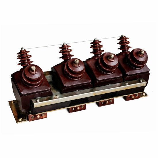
IEC 61869-3 Certified 11kV Voltage Transformer SZF-3 for Metering & Protection Applications
Introduction to the SZF-3 Voltage Transformer
The SZF-3 is a single-phase, indoor/outdoor-rated cast-resin voltage transformer (VT) designed for accurate voltage measurement and reliable protective relay operation in medium-voltage power systems operating at 11kV (IEC standard) or 10kV (domestic Chinese system). This instrument transformer leverages advanced vacuum pressure impregnation (VPI) epoxy resin technology to encapsulate its magnetic core and windings, ensuring superior dielectric strength, mechanical robustness, and environmental resistance compared to traditional oil-immersed alternatives.
Cast-resin insulation provides inherent fire safety, eliminating flammable fluids and reducing maintenance requirements. The solid dielectric structure resists moisture ingress, thermal cycling, and partial discharge degradation—critical for long-term reliability in harsh industrial or rural environments. Unlike oil-filled units, the SZF-3 requires no oil sampling, level monitoring, or containment systems, simplifying installation and lifecycle management.
Typical deployment scenarios include utility substations, industrial plant switchyards, renewable energy collector substations, and commercial building distribution panels where precise voltage transformation is essential for revenue metering, fault detection, and system monitoring.
Operating Principle of Cast-Resin Insulation
The SZF-3 employs a VPI (Vacuum Pressure Impregnation) process using cycloaliphatic epoxy resin to fully encapsulate the primary and secondary windings along with the grain-oriented electrical steel (GOES) core. During manufacturing, the wound assembly is placed in a vacuum chamber to remove air pockets, then impregnated under pressure with degassed resin. Subsequent curing at controlled temperatures yields a monolithic, void-free structure with high tracking resistance (CTI > 600 V) and excellent thermal conductivity (0.8–1.2 W/m·K).
This solid insulation system achieves a partial discharge inception voltage (PDIV) exceeding 1.2 times the rated system voltage (i.e., >13.2 kV), well above the IEC 61869-3 requirement of ≥1.1 × Um. The absence of liquid dielectrics eliminates risks associated with leakage, oxidation, or gas generation under fault conditions. Furthermore, the resin’s coefficient of thermal expansion closely matches that of copper and steel, minimizing mechanical stress during thermal transients.
Advantages Over Oil-Immersed Designs
Compared to conventional oil-immersed VTs, the SZF-3 offers significant operational and safety benefits. First, it is inherently non-flammable—classified as F1 per IEC 61869-3—making it suitable for indoor installations without fire barriers. Second, its maintenance-free design eliminates routine oil testing, dehydration, or gasket replacement. Third, the compact footprint (typically 30% smaller than equivalent oil units) allows denser panel layouts in space-constrained switchgear.
Environmental resilience is another key advantage: the SZF-3 operates reliably from -40°C to +40°C ambient temperature with relative humidity up to 95% (non-condensing) and at altitudes up to 1,000 meters without derating. Its IP54-rated enclosure protects against dust and water splashes, enabling direct outdoor mounting on poles or structures. Additionally, the absence of oil prevents soil contamination during end-of-life disposal, aligning with modern sustainability mandates.
Typical Application Overview
The SZF-3 serves dual roles in power systems: providing scaled-down secondary voltages (typically 100 V or 110 V) for revenue-grade metering and delivering accurate waveform reproduction for protective relays during faults. In 11kV radial distribution networks, it enables kWh billing accuracy within Class 0.2 or 0.5 per IEC 61869-3. For protection, its Class 3P or 6P accuracy ensures correct operation of overvoltage, undervoltage, and directional earth-fault relays even under transient conditions.
Common installations include ring main units (RMUs), metal-clad switchgear, and pad-mounted transformers. In solar PV farms, the SZF-3 monitors grid voltage at the point of interconnection, supporting anti-islanding and voltage ride-through functions. Its low burden rating (as low as 10 VA) minimizes loading effects on sensitive digital meters and IEDs (Intelligent Electronic Devices).
Technical Specifications
The SZF-3 adheres strictly to IEC 61869-3 and GB/T 20840.3, with verified performance across electrical, thermal, and mechanical parameters. Below is a representative specification table for standard configurations:
| Parameter | Value |
|---|---|
| System Voltage (Um) | 12 kV (IEC); 11.5 kV (GB) |
| Rated Primary Voltage | 11,000 / √3 V (phase-to-earth) |
| Rated Secondary Voltage | 100 / √3 V or 110 / √3 V |
| Voltage Ratio | 11,000 : 100 or 11,000 : 110 |
| Accuracy Class (Metering) | 0.2, 0.5 |
| Accuracy Class (Protection) | 3P, 6P |
| Rated Output (per winding) | 10–100 VA (configurable) |
| Insulation Level (LI/AC) | 75 kV / 28 kV (1 min) |
| Short-Time Thermal Withstand | 1 second at 100× rated current |
| Core Material | Grain-Oriented Electrical Steel (GOES), 0.23–0.27 mm thickness |
| Insulation System | VPI Epoxy Resin, Class F (155°C) |
| Service Conditions | Indoor/Outdoor, -40°C to +40°C, ≤95% RH, ≤1,000 m altitude |
Electrical Performance Parameters
The SZF-3 delivers voltage transformation with minimal phase displacement and ratio error. For Class 0.2 metering, the ratio error must not exceed ±0.2% and phase error ≤±10 minutes at 25–100% of rated voltage and 25–100% of rated burden. Under protection duty (Class 3P), ratio error remains within ±3% and phase error ≤±120 minutes at 5%–120% of rated voltage and up to 100% burden. These tolerances are validated during factory type tests per IEC 61869-3 Clause 7.
The transformer exhibits low magnetizing current (<0.5% of rated primary current at 1.9 × Un), ensuring stable operation under light-load or open-circuit conditions. Its thermal design supports continuous operation at 1.2 × rated voltage for 8 hours without exceeding insulation class limits. The short-circuit withstand capability—tested at 100 times rated secondary current for 1 second—ensures survival during downstream faults.
Environmental and Mechanical Ratings
Designed for global deployment, the SZF-3 meets IEC 60068-2 environmental test standards. It withstands salt fog (IEC 60068-2-11), damp heat cyclic (IEC 60068-2-30), and vibration (IEC 60068-2-6) without performance degradation. The molded resin housing includes UV stabilizers for outdoor use, preventing surface cracking or chalking after 10+ years of sun exposure.
Mounting is via M12 stainless steel bolts through integral flanges, with creepage distance ≥240 mm for 12 kV systems (pollution degree 3). Terminal blocks accommodate 16–50 mm² copper conductors, rated for 90°C operation. The unit weighs approximately 28 kg, facilitating manual handling during installation.
Typical Applications
The SZF-3 voltage transformer is engineered for versatility across diverse power infrastructure segments, delivering precision and reliability where accurate voltage sensing is mission-critical.
Substation Secondary Metering
In 11kV/0.4kV distribution substations, the SZF-3 supplies secondary voltage signals to revenue meters for billing purposes. Installed on the 11kV busbar, it steps down phase-to-earth voltage to 100/√3 V, interfacing with Class 0.2S static kWh meters. Its low phase error ensures compliance with EN 50470-1 and DL/T 614 standards for tariff accuracy. In smart grid deployments, it feeds data to AMI (Advanced Metering Infrastructure) concentrators, enabling remote load profiling and loss analysis. The cast-resin design eliminates oil-related maintenance in confined indoor rooms, enhancing safety for utility personnel.
Industrial Power Distribution Systems
Heavy industries—such as cement plants, steel mills, and chemical facilities—rely on the SZF-3 for both metering and motor protection. Here, it interfaces with multifunction relays (e.g., Siemens 7SJ, SEL-351) to detect undervoltage events that could stall critical motors. The VT’s Class 6P accuracy ensures correct relay tripping even during deep voltage sags (down to 5% Un). Its robust resin housing resists chemical fumes and airborne particulates common in such environments. Multiple secondary windings can be specified—one for metering (0.5 class) and another for protection (3P)—optimizing performance for each function.
Renewable Energy Integration
In solar and wind farms, the SZF-3 monitors grid voltage at the 11kV collection point. It enables anti-islanding protection by detecting voltage deviations beyond ±10% of nominal, triggering inverter disconnection per IEEE 1547 or GB/T 19964. Its fast response time (<20 ms) captures transient overvoltages caused by sudden load rejection. The VT’s low thermal drift ensures consistent calibration across diurnal temperature swings, critical for SCADA-based performance ratio calculations. Outdoor-rated models are directly mounted on tracker combiner boxes or step-up transformer pads.
Rural and Suburban Distribution Networks
For utilities serving dispersed loads, the SZF-3 is deployed on pole-top platforms or underground RMUs. Its compact size fits within standard 11kV switchgear bays, while its maintenance-free nature reduces truck rolls in remote areas. In China’s rural electrification programs, it supports 10kV system upgrades (equivalent to 11kV IEC) with GB/T 20840.3 compliance. The unit’s high insulation level (75 kV LI) withstands lightning surges common in overhead line networks, protecting downstream meters from impulse damage.
Compliance with International Standards
The SZF-3 is certified to IEC 61869-3:2011 (“Instrument transformers – Part 3: Additional requirements for inductive voltage transformers”) and fully aligned with China’s GB/T 20840.3-2013 standard, ensuring global interoperability and regulatory acceptance.
IEC 61869-3 Compliance Details
IEC 61869-3 defines performance, testing, and marking requirements for inductive VTs. The SZF-3 meets all mandatory clauses, including:
– Accuracy class definitions (Clause 5.2)
– Rated insulation levels (Table 2: 75/28 kV for 12 kV Um)
– Temperature rise limits (≤60 K for resin, measured by resistance method)
– Partial discharge limits (<10 pC at 1.2 × Um/√3)
- Type, routine, and special tests (Clauses 7–9)
Factory tests include power frequency withstand (28 kV, 1 min), induced overvoltage (148 V, 60 Hz, 30 s), and accuracy verification across burden and voltage ranges. Each unit bears an IEC-compliant nameplate listing Um, ratio, accuracy classes, outputs, and serial number traceable to test records.
Alignment with GB/T 20840.3
GB/T 20840.3 mirrors IEC 61869-3 but specifies 10kV as the nominal system voltage (vs. 11kV IEC). The SZF-3 accommodates both by design: its primary winding is rated for 11,000 V (IEC) but operates safely on 10,000 V systems with identical accuracy. Key GB-specific requirements include:
– Short-time thermal current: 100 × In for 1 s (same as IEC)
– Burden standardization: 10, 15, 30, 50, 100 VA
– Marking in Chinese characters alongside English
All SZF-3 units shipped to China undergo CNAS-accredited testing per GB/T 20840.3, with certificates issued by CEPREI or similar bodies.
Key Differences Between IEC and Domestic Standards
While technically harmonized, subtle differences exist:
– **Voltage Reference**: IEC uses 11kV (Um=12kV); GB uses 10kV (Um=11.5kV). The SZF-3’s design margin covers both.
– **Accuracy Verification**: GB requires testing at 80%, 100%, and 120% Un; IEC adds 5% and 20% for protection classes.
– **Marking**: GB mandates domestic manufacturer info and CCC logo if applicable.
Despite these, the SZF-3’s universal design avoids model proliferation—single SKU serves global markets.
On-Site Testing Procedures
Post-installation verification ensures the SZF-3 performs within specifications. All tests follow IEC 60060-1 and IEC 61869-3 guidelines.
Insulation Resistance Test
Measure insulation resistance between windings and ground using a 2,500 V DC megohmmeter. Apply test voltage for 1 minute. Acceptance criterion: ≥1,000 MΩ at 20°C. Correct for temperature using R₂₀ = Rₜ × 1.5(t−20)/10. Low readings indicate moisture ingress or resin cracking—requiring drying or replacement.
Turns Ratio Test
Apply 100–200 V AC to the primary and measure secondary voltage. Calculate ratio = Vp/Vs. Compare to nameplate value. Tolerance: ±0.2% for metering class, ±3% for protection class. Use a dedicated ratio tester (e.g., Omicron CT Analyzer) for best accuracy. Deviations suggest winding shorts or incorrect tap selection.
Polarity Test
Verify reducing polarity per IEC 61869-3 Figure 3. Connect a 6–12 V battery across primary terminals (H1+, H2−). Momentarily close the circuit while monitoring secondary with a DC voltmeter. A positive kick confirms correct polarity (X1 corresponds to H1). Incorrect polarity causes metering errors and relay misoperation.
Power Frequency Withstand Voltage Test
Apply 28 kV RMS, 50 Hz between primary and grounded secondary/core for 1 minute. Use a calibrated test transformer with overcurrent trip (≤100 mA). No flashover or breakdown permitted. This validates insulation integrity after transport and installation stresses.
Open-Circuit Characteristic Test
Gradually increase primary voltage from 0 to 190 V (≈1.9 × rated secondary) while measuring excitation current. Plot V vs. I curve. Excessive current (>0.5% In at 100 V) indicates core saturation or shorted turns. This test is critical for VTs used in ferroresonance-prone networks.
Preventive Maintenance Guide
Though maintenance-free by design, periodic checks extend service life beyond 25 years.
Annual Visual and Functional Inspection
Inspect for:
– Surface cracks, tracking, or discoloration on resin
– Loose terminal connections (torque: 25 N·m for M10)
– Corrosion on mounting hardware
– Cleanliness of terminals (use dry cloth; no solvents)
Verify secondary voltage under load using a calibrated meter. Drift >1% from baseline warrants further testing.
Five-Year Comprehensive Maintenance
Perform full suite of on-site tests (Section 5). Additionally:
– Measure winding resistance (primary: ~150 Ω ±10%; secondary: ~0.5 Ω ±10%)
– Check grounding continuity (<0.1 Ω between flange and earth bar)
- Review historical data for trend analysis (e.g., rising excitation current)
Replace if partial discharge exceeds 20 pC during on-site PD testing.
Maintenance Intervals and Fault Diagnosis
| Interval | Action | Fault Indicator |
|---|---|---|
| Annually | Visual + voltage check | Cracks, overheating marks, voltage error >1% |
| 5 Years | Full electrical tests | Ratio error out of class, IR <500 MΩ |
| After Fault | Withstand + ratio test | Flashover, relay misoperation |
Common failures include terminal corrosion (due to galvanic mismatch) and resin delamination (from thermal cycling). Neither is repairable—unit replacement is required.
Conclusion
The SZF-3 11kV cast-resin voltage transformer represents a benchmark in medium-voltage instrumentation, combining IEC 61869-3-certified accuracy with the ruggedness demanded by modern power systems. Its VPI epoxy resin encapsulation delivers unmatched fire safety, environmental resilience, and maintenance-free operation over a projected service life of 25–30 years. By supporting both metering (Class 0.2/0.5) and protection (Class 3P/6P) functions in a single compact unit, it reduces inventory complexity and installation costs for utilities and industrial users alike.
Compliance with both international (IEC) and domestic (GB/T) standards ensures seamless integration into global grids, whether deployed in urban substations, remote renewable sites, or heavy industrial facilities. Rigorous factory and field testing protocols guarantee performance consistency, while the GOES core and precision winding techniques minimize errors under dynamic load conditions. As distribution networks evolve toward digitalization and decentralization, the SZF-3 provides the foundational voltage sensing accuracy required for smart metering, adaptive protection, and grid-edge intelligence—making it a future-proof investment for critical infrastructure.