Article Content
LSZY-10 11kV Cast-Resin Current Transformer for Substation Metering and Protection – IEC 61869-2 Certified
Introduction to the LSZY-10 Current Transformer
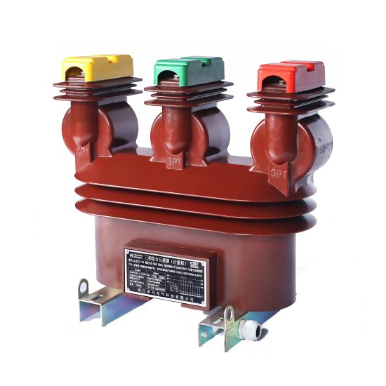
The LSZY-10 is a high-reliability, cast-resin insulated current transformer (CT) engineered for accurate metering and dependable protection in 11kV (IEC-rated) or 10kV (domestic system) medium-voltage networks. Designed in strict compliance with IEC 61869-2 and GB/T 20840.2, this device leverages vacuum pressure impregnation (VPI) epoxy resin technology to deliver superior dielectric strength, environmental resilience, and long-term operational stability. Unlike traditional oil-immersed CTs, the LSZY-10 eliminates fire hazards, oil leakage risks, and maintenance-intensive fluid management, making it ideal for both indoor substations and outdoor pole-mounted installations.
Operating Principle of Cast-Resin Insulation
Cast-resin insulation in the LSZY-10 employs a two-stage VPI process where high-purity epoxy resin is vacuum-degassed and then pressure-injected around the primary conductor and secondary windings. This creates a monolithic, void-free solid dielectric structure with excellent tracking resistance (CTI > 600) and thermal class F (155°C) endurance. The absence of air pockets prevents partial discharge inception below 10 pC at 1.2 × Um/√3 (7.6 kV), ensuring stable performance over decades. The resin matrix also provides mechanical rigidity, protecting the GOES (grain-oriented electrical steel) core from vibration-induced degradation—a critical factor in industrial environments with harmonic-rich loads.
Advantages Over Oil-Immersed Designs
Compared to oil-filled CTs, the LSZY-10 offers significant operational and safety benefits. It is inherently non-flammable (IEC 60695 glow-wire tested at 960°C), eliminating explosion risks in confined spaces. Its maintenance-free design removes the need for periodic oil sampling, moisture testing, or gasket replacement. Furthermore, the compact footprint—enabled by higher dielectric strength of epoxy versus oil—reduces switchgear bay dimensions. Environmental compliance is enhanced as the unit contains no PCBs or hydrocarbons, aligning with RoHS and WEEE directives. In coastal or high-humidity regions, the hydrophobic resin surface resists salt fog and condensation, preventing flashovers that plague porcelain-oil alternatives.
Typical Application Overview
The LSZY-10 is deployed across utility distribution networks, industrial plants, and renewable energy interconnection points. Primary use cases include feeder metering at 10kV ring main units (RMUs), differential protection of distribution transformers, and revenue-grade energy measurement in commercial substations. Its dual-core configuration (e.g., 0.5/5P10) allows simultaneous connection to billing meters and overcurrent relays without cross-interference. With a standard burden rating of 15–30 VA per core and accuracy maintained up to 120% of rated current, it supports modern digital relays requiring low excitation impedance. Typical installations span urban underground networks, rural overhead lines, and solar farm collector substations operating at 50 Hz.
Technical Specifications
The LSZY-10 adheres to precise electrical and mechanical parameters defined by international and Chinese standards. Key specifications are summarized below:
| Parameter | Value |
|---|---|
| Rated System Voltage (Um) | 11 kV (IEC), 10 kV (GB) |
| Primary Current (Ip) | 50–3000 A (standard ratios: 100/5, 200/5, 400/5, etc.) |
| Secondary Current (Is) | 1 A or 5 A |
| Accuracy Classes | Metering: 0.2S, 0.5S; Protection: 5P10, 5P20 |
| Rated Burden | 2.5–30 VA (per core) |
| Insulation Level | Power Frequency Withstand: 28 kV rms / 1 min Lightning Impulse: 75 kV peak (1.2/50 μs) |
| Short-Time Thermal Current | 25 kA for 1 s (Ith) |
| Dynamic Withstand Current | 62.5 kA peak (Idyn) |
| Ambient Temperature Range | –40°C to +40°C |
| Altitude Limit | ≤ 1000 m (derating required above) |
| Relative Humidity | ≤ 95% (non-condensing) |
| Core Material | GOES silicon steel, grain-oriented, 0.3 mm thickness |
| Insulation System | VPI epoxy resin, UL 94 V-0 flammability rated |
Standard Service Conditions
The LSZY-10 is rated for continuous operation under IEC 60060-1 standard atmospheric conditions: ambient temperature between –40°C and +40°C, daily average not exceeding +35°C. Relative humidity may reach 95% provided condensation does not occur on terminals. Installation altitude must not exceed 1000 m above sea level; for altitudes between 1000–2000 m, the power frequency withstand voltage must be reduced by 1% per 100 m increment. The unit is designed for 50 Hz systems but can operate at 60 Hz with derated burden (typically 85% of 50 Hz rating). Pollution degree is classified as III per IEC 60664-1, suitable for industrial atmospheres with conductive dust.
Electrical Performance Tolerances
Current error and phase displacement comply strictly with IEC 61869-2 Table 3 limits. For a 0.5S class metering core at 100% rated current and 25°C, current error must be within ±0.5%, and phase displacement ≤ ±30 minutes. Protection cores (5P10) exhibit composite error ≤ 5% at 10× rated current with rated burden. Ratio tolerance is ±0.25% for standard ratios. Excitation characteristics are guaranteed such that knee-point voltage exceeds 1.5× rated secondary voltage under 5P conditions. Saturation flux density of the GOES core is limited to 1.7 T to prevent remanence-induced ratio shift after fault clearance.
Typical Applications
The LSZY-10’s robust design enables deployment across diverse medium-voltage infrastructure scenarios requiring precision and reliability.
Substation Secondary Metering
In 10kV/0.4kV distribution substations, the LSZY-10 provides revenue-grade current signals to AMI (Advanced Metering Infrastructure) systems. Installed on outgoing feeders, its 0.2S or 0.5S metering core interfaces with Class 0.5S kWh meters, ensuring billing accuracy per EN 50470-1. The dual-core variant allows concurrent connection to SCADA RTUs for load profiling. For example, a 400/5 A, 0.2S/5P10 LSZY-10 installed at a municipal utility substation delivers ±0.2% current error at 5–120% Ip, supporting time-of-use tariff calculations. Secondary terminals are IP54-rated to prevent dust ingress during meter reading cycles.
Industrial Power Distribution
Heavy industries—such as steel mills, chemical plants, and data centers—use the LSZY-10 for motor protection and harmonic monitoring. Its high short-circuit withstand (25 kA/1s) protects against arc-flash events during motor starting surges. In a 10kV motor control center (MCC), an LSZY-10 with 5P20 protection core feeds numerical relays (e.g., Siemens 7SJ62) that detect phase unbalance or ground faults within 20 ms. The cast-resin body resists chemical vapors (e.g., chlorine, ammonia) that degrade oil seals. Core saturation is minimized even with 15% THD currents due to the high-permeability GOES material.
Renewable Energy Integration
Solar and wind farms employ the LSZY-10 at collector substation incomers for anti-islanding protection and export metering. At a 20 MW solar plant, LSZY-10 units (600/1 A, 0.5S/5P10) monitor bidirectional power flow to grid-tie inverters. The 1 A secondary reduces copper losses over long cable runs to the control room. During cloud transients causing rapid irradiance changes, the CT maintains linearity within ±0.5% error from 5% to 120% Ip. Lightning impulse withstand (75 kV) safeguards against surges from nearby strikes on overhead collector lines.
Rural and Suburban Distribution Networks
Pole-mounted LSZY-10 CTs enable smart grid upgrades in legacy 10kV overhead networks. Mounted on cutout fuse supports, they feed fault indicators and sectionalizers for automated outage restoration. A typical rural application uses 200/5 A, 5P10 units to detect single-phase-to-ground faults with 500 mA sensitivity. The UV-stabilized resin housing withstands 10,000+ hours of accelerated weathering (IEC 60068-2-5). In high-altitude villages (>2500 m), derated models maintain 20 kV power frequency withstand via adjusted resin formulation.
Compliance with International Standards
The LSZY-10 is certified to both global and Chinese regulatory frameworks, ensuring interoperability and safety across markets.
IEC 61869-2 Compliance Details
Per IEC 61869-2:2012, the LSZY-10 undergoes type tests including temperature rise (≤ 60 K for windings), short-circuit (25 kA/1s without deformation), and partial discharge (< 10 pC at 7.6 kV). Accuracy verification follows Clause 6.3 using calibrated reference CTs traceable to NIM (China) or PTB (Germany). The standard mandates that protection cores maintain specified error limits at 100% and 120% rated current—verified via burden sweep from 25% to 100% of rated VA. Markings include In, accuracy class, burden, and polarity dots per Figure 102 of the standard.
Alignment with GB/T 20840.2
GB/T 20840.2-2014 (identical adoption of IEC 61869-2) requires additional domestic validations. These include seismic testing (0.3g horizontal acceleration per GB/T 13540) and salt fog resistance (1000 h neutral salt spray per GB/T 10125). Chinese utilities often specify 0.2S class for all new metering installations, which the LSZY-10 meets with margin (typical error: ±0.15% at 100% Ip). The standard also defines terminal torque values: M6 studs require 8–10 N·m tightening to prevent thermal runaway at high currents.
Key Differences Between IEC and GB Standards
While technically harmonized, practical differences exist. GB/T 20840.2 mandates factory routine tests for every unit (including ratio and polarity), whereas IEC permits sample testing for batches ≤ 50 units. Chinese grid codes (e.g., Q/GDW 1376) often require 5P20 instead of 5P10 for urban feeders, demanding higher saturation margins. Additionally, GB specifies minimum creepage distance of 240 mm/kV for pollution degree III—achieved via ribbed resin housing design. Certification bodies differ: CQC (China Quality Certification) issues GB marks, while IEC compliance is validated by TÜV or SGS.
On-Site Testing Procedures
Post-installation verification ensures the LSZY-10 performs within specification before energization.
Insulation Resistance Test
Using a 2500 V DC megohmmeter, measure insulation resistance between primary-to-secondary, primary-to-ground, and secondary-to-ground. Acceptance criterion: ≥ 1000 MΩ at 20°C. Correct for temperature using RT = R20 × 2(20–T)/10. Low readings (< 500 MΩ) indicate moisture ingress or resin cracking—requiring drying or replacement. Perform before and after power frequency withstand test to detect latent defects.
Turns Ratio Test
Apply 1–5 V AC at 50 Hz to the secondary winding and measure induced primary voltage (open-circuit). Calculate ratio as Vs/Vp; compare to nameplate. Tolerance: ±0.25% for metering cores, ±0.5% for protection. Alternatively, use a dedicated CT analyzer (e.g., Omicron CT Analyzer) injecting 1–10 A into primary and measuring secondary current. Deviations >1% suggest turn-to-turn shorts or incorrect tap selection.
Polarity Test
Verify reducing polarity per IEC 61869-2 Figure 102. Connect a 1.5 V battery momentarily between P1 and P2. Observe secondary voltage on a DC voltmeter: positive deflection at S1 confirms correct polarity. Incorrect polarity causes 180° phase shift, leading to false tripping in differential schemes. Document results with oscillograms if using relay test sets (e.g., Doble F6150).
Power Frequency Withstand Voltage Test
Apply 28 kV rms at 50 Hz between primary and grounded secondary/enclosure for 1 minute. Use a calibrated HV test set with overcurrent trip (≤ 100 mA). No flashover or disruptive discharge is permitted. Ramp voltage at 1 kV/s to avoid transient overstress. For field tests, reduce to 80% (22.4 kV) if performed after commissioning. Always discharge primary capacitance post-test via grounding stick.
Excitation (Knee-Point) Test
For protection cores, perform open-circuit excitation test per IEC 60044-1 Annex B. Gradually increase secondary voltage while measuring excitation current. Plot V-I curve; knee-point is where slope decreases by 45°. For 5P10, knee-point must exceed 1.5 × (Is × Zb + Rct × Is). Example: 5 A secondary, 15 VA burden → knee-point > 45 V. Low knee-point indicates core saturation risk during faults.
Preventive Maintenance Guide
Although maintenance-free by design, periodic checks extend service life beyond 30 years.
Periodic Inspection Protocol
Conduct visual and thermographic inspections annually. Check for: (1) surface cracks or tracking on resin housing, (2) terminal corrosion or overheating (ΔT > 15 K vs. ambient), (3) loose mounting hardware (torque to 25 N·m for M12 bolts). Use IR camera during peak load to detect hot spots at secondary connections. Clean housing with isopropyl alcohol if salt or carbon deposits accumulate. Record insulation resistance trends—decline >20% year-over-year warrants detailed diagnostics.
Maintenance Intervals and Fault Diagnosis
Follow this schedule:
| Interval | Action |
|---|---|
| Annual | Visual inspection, IR scan, insulation resistance |
| 5 Years | Ratio/polarity retest, excitation curve validation |
| 10 Years | Partial discharge measurement (if available) |
Common faults include: (1) Secondary open-circuit during operation—causes core saturation and dangerous overvoltages (> 10 kV); always short secondary before disconnecting meters. (2) Moisture ingress at terminal box—evidenced by white powder (hydrolysis byproducts); replace gasket and apply silicone sealant. (3) Core remanence after high-magnitude faults—demagnetize using decaying AC current at 120% Ip.
Conclusion
The LSZY-10 11kV cast-resin current transformer represents a benchmark in medium-voltage instrumentation, combining IEC 61869-2 and GB/T 20840.2 compliance with field-proven reliability. Its VPI epoxy resin insulation eliminates the fire and environmental liabilities of oil-filled alternatives, while the GOES silicon steel core ensures metrological precision across metering (0.2S/0.5S) and protection (5P10/5P20) applications. With a rated thermal short-circuit current of 25 kA for 1 second and lightning impulse withstand of 75 kV, it withstands the most demanding grid transients. The unit’s maintenance-free design, coupled with a service life exceeding 25–30 years under standard conditions, delivers significant lifecycle cost savings. Whether deployed in urban substations, industrial complexes, or renewable energy sites, the LSZY-10 provides the accuracy, safety, and durability required for modern power systems. Its adherence to international standards guarantees seamless integration with protective relays, revenue meters, and SCADA infrastructure worldwide.