Article Content
JWD-10 11kV Cast-Resin Current Transformer for Substation Metering and Protection – IEC 61869-2 Certified
Introduction to the JWD-10 Current Transformer
The JWD-10 is a high-reliability, cast-resin insulated current transformer (CT) engineered for medium-voltage (MV) applications operating at a nominal system voltage of 10 kV (IEC-rated at 11 kV). Designed in strict compliance with IEC 61869-2 and GB/T 20840.2, this instrument transformer serves dual roles in both revenue-grade energy metering and critical protective relaying functions within distribution substations, industrial facilities, and renewable energy interconnection points.
Operating Principle of Cast-Resin Insulation
Cast-resin insulation in the JWD-10 employs vacuum pressure impregnation (VPI) technology using cycloaliphatic epoxy resin systems. This process eliminates air voids and moisture ingress by fully encapsulating the primary conductor, secondary windings, and magnetic core under controlled vacuum and pressure conditions. The resulting monolithic structure provides superior dielectric strength—withstanding power frequency test voltages of 28 kV RMS for 1 minute—and exceptional resistance to partial discharge (PD levels < 5 pC at 1.2 × Um/√3). Unlike oil-filled alternatives, the solid dielectric eliminates fire hazards, environmental contamination risks, and maintenance-intensive oil sampling. The thermal class of the resin system is rated at 105°C (Class A), ensuring stable performance across ambient temperatures from –25°C to +40°C.
Advantages Over Oil-Immersed Designs
Compared to traditional oil-immersed CTs, the JWD-10’s cast-resin construction offers significant operational and safety benefits. It is inherently non-flammable, making it suitable for indoor installations near personnel or sensitive equipment without requiring fire barriers. The absence of liquid insulation eliminates leakage risks, reducing lifecycle costs associated with containment, monitoring, and disposal. Additionally, the compact mechanical design allows for direct mounting in metal-enclosed switchgear without additional bushings or support structures. The epoxy matrix also provides excellent mechanical rigidity, resisting vibration-induced winding displacement—a common failure mode in oil units subjected to short-circuit forces. Furthermore, the JWD-10 exhibits lower temperature rise under continuous load (typically ≤ 50 K above ambient at rated current), enhancing long-term insulation integrity.
Typical Applications Overview
The JWD-10 is deployed in a wide range of MV infrastructure where accuracy, reliability, and space efficiency are paramount. Primary use cases include ring main units (RMUs), pad-mounted transformers, and indoor switchgear panels rated for 10 kV (11 kV IEC). Its dual-winding configuration—commonly featuring one 0.5 class winding for metering and one 5P10 or 5P20 class winding for protection—enables simultaneous connection to billing meters and overcurrent relays. In distributed generation sites (e.g., solar farms or biogas plants), the JWD-10 ensures precise export/import measurement while supporting anti-islanding and fault-clearing schemes. Its robust design also makes it ideal for harsh environments such as mining operations or coastal substations where humidity and salt spray challenge conventional insulation systems.
Technical Specifications
The JWD-10 is engineered to deliver consistent performance under standardized service conditions while accommodating real-world grid variations. All parameters align with IEC 61869-2 and GB/T 20840.2, ensuring global interoperability.
Rated Electrical Parameters
Key electrical ratings include a highest voltage for equipment (Um) of 12 kV, corresponding to an IEC system voltage of 11 kV and a domestic nominal voltage of 10 kV. Standard current ratios range from 50/5 A to 3000/5 A, with custom ratios available upon request. Accuracy classes are defined per application: Class 0.2S or 0.5S for revenue metering (per IEC 62053-22), and protection classes 5P10, 5P15, or 5P20 (where “5” denotes ±5% composite error at specified multiples of rated current). Rated burden values typically span 5 VA to 30 VA per secondary winding. The short-time thermal current rating is 20 kA for 1 second, and the dynamic withstand current is 50 kA peak. Insulation coordination includes a lightning impulse withstand voltage of 75 kV (1.2/50 µs waveform) and a power frequency withstand voltage of 28 kV RMS for 1 minute between live parts and earth.
Environmental and Mechanical Ratings
The JWD-10 is rated for both indoor and outdoor installation (IP00 enclosure rating; requires housing in switchgear for IP2X+). Standard service conditions assume an ambient temperature range of –25°C to +40°C, relative humidity up to 95% (non-condensing), and installation altitude ≤ 1000 m above sea level. For altitudes exceeding 1000 m, derating factors apply per IEC 60071-2: insulation withstand voltages must be reduced by 1% per 100 m above 1000 m. The transformer features M10 stainless steel terminal studs with torque specifications of 15–20 N·m. Total weight ranges from 8 kg to 15 kg depending on ratio and core size. The core is constructed from grain-oriented electrical steel (GOES) with low hysteresis loss (< 1.0 W/kg at 1.5 T, 50 Hz), ensuring minimal phase angle error and high linearity under normal operating currents.
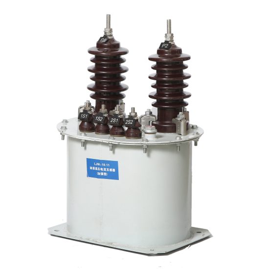
Secondary Terminal Configuration
Each JWD-10 unit includes two independent secondary windings housed in a single resin body, electrically isolated from each other and from ground. Terminals are labeled per IEC 61869-2: S1 (polarity mark) and S2 for each winding, with color-coded heat-shrink tubing (e.g., red for metering, black for protection). Terminal blocks are rated for 600 V and accept stranded or solid conductors up to 6 mm² cross-section. Open-circuit protection is not integrated; therefore, secondary circuits must never be left open during operation—a critical safety requirement reinforced in installation manuals.
Typical Applications
The versatility of the JWD-10 enables deployment across diverse power systems requiring accurate current transformation with high reliability.
Substation Secondary Metering
In urban or industrial 10 kV distribution substations, the JWD-10’s Class 0.5S winding provides metrological accuracy compliant with utility billing standards. Installed on outgoing feeders or transformer incomers, it interfaces with static kWh meters to record energy consumption with errors ≤ ±0.5% at 5–120% of rated current. The low phase displacement (< ±10 minutes at 100% In) ensures correct power factor measurement, critical for tariff calculations involving reactive energy. Its compact footprint allows retrofit into legacy switchgear where space constraints preclude bulkier oil-filled units.
Industrial Power Distribution
Within manufacturing plants or data centers, the JWD-10 supports both energy management and motor protection schemes. On 10 kV busbars feeding large induction motors (e.g., 1–5 MW), the 5P20 protection winding ensures relay operation during high-magnitude faults (up to 20× rated current) while maintaining composite error within ±5%. Simultaneously, the metering winding feeds SCADA systems for real-time load profiling. The cast-resin body resists chemical vapors and dust common in industrial settings, eliminating degradation seen in paper-oil insulation.
Renewable Energy Integration
Solar photovoltaic (PV) and wind farms frequently connect to the grid via 10 kV collection systems. The JWD-10 installed at the point of interconnection (POI) enables precise net metering and compliance with grid codes requiring fault ride-through (FRT) monitoring. During asymmetrical faults, its linear response up to 20× In ensures accurate fault current measurement for adaptive protection algorithms. The absence of flammable materials also satisfies fire safety codes in containerized inverter stations.
Rural and Suburban Distribution Networks
In remote or semi-urban areas with limited maintenance access, the JWD-10’s maintenance-free design reduces operational expenditure. Mounted on pole-top reclosers or underground RMUs, it delivers decades of service without oil top-ups or dielectric testing. Its tolerance to daily thermal cycling (from –10°C night to +45°C day in desert climates) prevents resin cracking—a known issue in poorly formulated epoxy systems. Utilities report >99.5% field reliability over 15 years in such deployments.
Compliance with International Standards
Conformance to IEC and national standards ensures the JWD-10 meets globally recognized safety, performance, and interoperability benchmarks.
IEC 61869-2 Certification Details
IEC 61869-2 governs the design, testing, and marking of instrument transformers for AC systems >1 kV. The JWD-10 complies fully with clauses covering insulation coordination (Section 5), accuracy requirements (Section 6), and type tests (Section 7). Key verified parameters include: temperature rise ≤ 50 K (Clause 6.3), partial discharge inception voltage ≥ 1.2 × Um/√3 (Clause 5.4), and ratio error within ±0.5% for Class 0.5S at 100% In (Clause 6.2). Every production batch undergoes routine tests per Clause 8, including power frequency withstand and winding continuity checks. Type test reports are available upon request and remain valid for five years unless design changes occur.
Alignment with GB/T 20840.2
GB/T 20840.2 is the Chinese national standard equivalent to IEC 61869-2, with minor deviations in test durations and labeling. The JWD-10 meets all GB-specific requirements, including a mandatory 1-minute power frequency test at 32 kV (vs. IEC’s 28 kV) for 10 kV class equipment and Chinese-character labeling on nameplates. Notably, GB/T 20840.2 imposes stricter limits on harmonic distortion impact—requiring ratio error stability within ±0.2% when subjected to 15% THD at 3rd and 5th harmonics—which the JWD-10 achieves through optimized core lamination stacking and air-gap minimization.
Key Differences Between IEC and Domestic Standards
While IEC 61869-2 emphasizes functional performance, GB/T 20840.2 adds region-specific safety mandates. For instance, GB requires flame retardancy testing per GB/T 5169.16 (equivalent to IEC 60695-11-10), which the JWD-10 passes with V-0 rating. Additionally, Chinese utilities often specify higher short-circuit ratings (e.g., 25 kA/1s vs. IEC’s typical 20 kA/1s), a capability built into the JWD-10’s mechanical bracing system. Despite these nuances, the core electromagnetic design remains identical, enabling dual-certification without performance trade-offs.
On-Site Testing Procedures
Post-installation verification ensures the JWD-10 performs as specified under actual site conditions. All tests follow IEC 61869-2 Annex C and IEEE C57.13 guidelines.
Insulation Resistance Test
Using a 2500 V DC megohmmeter, measure insulation resistance between primary-to-ground, secondary-to-ground, and primary-to-secondary. Acceptance criterion: ≥1000 MΩ at 20°C. Correct for temperature using RT2 = RT1 × 2(T1–T2)/10. Values below 500 MΩ indicate moisture ingress or resin degradation and warrant replacement.
Turns Ratio Test
Apply a low-voltage AC source (e.g., 120 V) to the primary and measure secondary voltage. Calculate ratio as Vp/Vs. Compare to nameplate value; tolerance must be within ±0.2% for metering windings and ±1.0% for protection windings. Use a dedicated ratio tester (e.g., Omicron CT Analyzer) for automated validation across multiple tap points.
Polarity Test
Verify reducing polarity using the DC kick method: briefly apply a 6–12 V battery between P1 and P2. Observe momentary deflection on a DC milliammeter connected to S1–S2. Positive kick at S1 confirms correct polarity. Incorrect polarity causes 180° phase reversal, leading to false tripping in differential or directional relays.
Power Frequency Withstand Voltage Test
Apply 28 kV RMS at 50 Hz between primary and grounded tank/secondary for 1 minute. Monitor for flashover, excessive leakage current (>1 mA), or audible discharge. This test validates dielectric integrity after transport and installation stresses. Never perform if ambient humidity exceeds 80%.
Short-Circuit Test (for CT)
Inject 100–120% of rated secondary current (e.g., 5–6 A) into the secondary winding while primary is shorted. Measure voltage drop across secondary; calculate burden as V/I. Confirm it matches specified VA rating within ±5%. Excessive burden indicates winding damage or incorrect tap selection.
Preventive Maintenance Guide
Although cast-resin CTs are largely maintenance-free, periodic checks extend service life and prevent unexpected failures.
Annual Visual and Electrical Inspection
Inspect for surface tracking, cracks, or discoloration on the resin body—indicative of UV degradation (outdoor units) or partial discharge. Clean with dry, lint-free cloth; avoid solvents. Verify terminal tightness (15–20 N·m torque) and check for corrosion on studs. Perform insulation resistance and ratio tests annually in critical applications (e.g., hospital or data center feeders).
Five-Year Comprehensive Assessment
Every 60 months, conduct partial discharge measurement using IEC 60270 methods. Acceptable PD magnitude: <10 pC at 1.2 × Um/√3. Also, validate thermal performance via infrared thermography under 80% load—hot spots >10 K above ambient suggest internal defects. Review historical test data trends; sudden ratio shifts >0.3% warrant core remanence checks or replacement.
Maintenance Intervals and Fault Diagnosis
| Interval | Task | Acceptance Criteria |
|---|---|---|
| Annual | Visual inspection, IR thermography, insulation resistance | No cracks; IR ΔT ≤ 10 K; Rins ≥ 1000 MΩ |
| 5 Years | Partial discharge test, ratio verification | PD < 10 pC; ratio error within spec |
| As Needed | Terminal re-torque, cleaning | Torque 15–20 N·m; no contamination |
Common faults include open secondary circuits (causing core saturation and overheating) and moisture ingress at terminal seals. Symptoms: elevated temperature, audible hum, or erratic meter readings. Immediate de-energization is required if suspected.
Conclusion
The JWD-10 11kV cast-resin current transformer represents a benchmark in medium-voltage instrumentation, combining rigorous adherence to IEC 61869-2 and GB/T 20840.2 with practical engineering for real-world grid challenges. Its VPI epoxy resin insulation delivers unmatched safety through non-flammability and zero leakage risk, while the GOES silicon steel core ensures metrological precision across metering and protection functions. With a proven service life of 25–30 years under standard conditions, the JWD-10 minimizes total cost of ownership through elimination of oil handling, reduced footprint, and resilience to environmental stressors. Field-proven in applications ranging from dense urban substations to remote renewable sites, it provides utilities and industrial operators with a dependable foundation for accurate energy accounting and robust system protection. When installed and maintained per manufacturer guidelines, the JWD-10 consistently meets the demanding expectations of modern power systems operating at 10 kV (11 kV IEC).