Article Content
Introduction to the LFS-10 Current Transformer
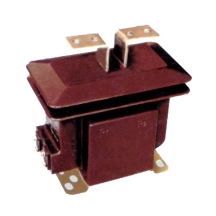
The LFS-10 is a high-reliability, cast-resin insulated current transformer (CT) engineered for critical metering and protection functions in medium-voltage power systems operating at nominal system voltages up to 11 kV. Designed in strict accordance with IEC 61869-2 and GB/T 20840.2, this device exemplifies modern advancements in solid-insulation technology for instrument transformers deployed in indoor switchgear, ring main units (RMUs), and compact secondary substations.
Cast-Resin Insulation Technology Principles
Cast-resin insulation utilizes thermosetting epoxy resins—typically cycloaliphatic or bisphenol-A-based formulations—filled with silica or alumina to enhance thermal conductivity and reduce coefficient of thermal expansion (CTE). The resin is vacuum-cast around the primary conductor and secondary windings under controlled temperature and pressure to eliminate voids and ensure homogeneous dielectric integrity. This process yields a monolithic, hermetically sealed structure with superior resistance to partial discharge (PD), moisture ingress, and environmental degradation compared to traditional oil-paper or gas-insulated alternatives.
Key material properties include:
- Dielectric strength: ≥20 kV/mm
- Tracking resistance (CTI): >600 V (IEC 60112)
- Thermal class: F (155°C) or H (180°C), depending on core and winding design
- Flame retardancy: UL 94 V-0 compliant
Advantages Over Oil-Immersed Designs
In contrast to oil-filled CTs, the LFS-10’s dry-type construction eliminates fire hazards, environmental contamination risks, and maintenance-intensive oil sampling or degassing procedures. The absence of liquid insulation also permits unrestricted orientation during installation and eliminates concerns about oil expansion tanks or leakage seals. Furthermore, cast-resin CTs exhibit lower lifecycle costs in urban or indoor environments due to reduced regulatory compliance burdens (e.g., no SPCC plans under EPA regulations) and compatibility with confined-space safety protocols.
LFS-10 Specific Innovations
The LFS-10 incorporates several engineering refinements:
- Dual-core configuration: One core optimized for 0.2S/0.5S metering accuracy; the other for 5P10/5P20 protection class performance.
- Graded electric field control via embedded stress-relief electrodes within the resin matrix to suppress surface flashover at terminations.
- Precision-wound secondary coils using oxygen-free copper (OFC) with tight tolerance on turn count and inter-turn spacing to minimize phase error and ratio deviation.
- Integrated thermal monitoring provisions (optional) for predictive maintenance in high-load applications.
These features collectively ensure long-term stability under continuous duty and transient fault conditions.
Technical Specifications and Design Parameters
The LFS-10 is rated for operation in 50/60 Hz AC power systems with defined electrical, thermal, and mechanical limits as detailed below.
Rated Voltage, Current, and Frequency
| Parameter | Value | Standard Reference |
|---|---|---|
| System Voltage (Um) | 12 kV (max) | IEC 61869-2, Table 1 |
| Rated Primary Current (Ip) | 50–3000 A (standard); up to 5000 A (custom) | IEC 61869-2, Clause 5.2 |
| Rated Secondary Current (Is) | 1 A or 5 A | IEC 61869-2, Clause 5.3 |
| Rated Frequency | 50 Hz or 60 Hz | IEC 61869-2, Clause 5.4 |
Insulation Levels
The insulation coordination of the LFS-10 adheres to IEC 60071-1 for overvoltage protection:
- Power Frequency Withstand Voltage (1 min): 28 kV RMS (phase-to-earth)
- Lightning Impulse Withstand Voltage (BIL): 75 kV peak (1.2/50 μs waveform)
These levels exceed the minimum requirements for 11 kV class equipment (20 kV/60 kV) to provide additional safety margin in polluted or high-altitude installations (>1000 m ASL).
Accuracy Classes
The LFS-10 supports dual-functionality through segregated cores:
- Metering Core: Accuracy classes 0.2S, 0.5S per IEC 61869-2, suitable for revenue-grade energy measurement. Ratio error ≤ ±0.2% and phase displacement ≤ ±10 minutes at 100% In.
- Protection Core: Accuracy classes 5P10, 5P20, ensuring ≤5% composite error at 10× or 20× rated current, respectively. Saturation factor (Kssc) ≥10 or 20 as specified.
Thermal and Dynamic Performance
Thermal short-time current rating (Ith) is typically 20–40 kA for 1 second, depending on primary conductor cross-section. The dynamic withstand current (Idyn) is rated at 2.5 × Ith, satisfying electromagnetic force resilience during asymmetrical faults. Temperature rise under continuous rated current is limited to 60 K above ambient (40°C) for windings, verified via hot-spot measurement per IEC 61869-2 Annex C.
IEC 61869 Compliance and Standards
IEC 61869-2 Specific Requirements
IEC 61869-2:2012 (“Instrument transformers – Part 2: Additional requirements for current transformers”) governs the design, testing, and marking of low-power and conventional CTs up to 36 kV. The LFS-10 complies with all mandatory clauses, including:
- Clause 6: Insulation requirements (power frequency and impulse tests)
- Clause 7: Temperature rise limits
- Clause 8: Short-circuit withstand capability
- Clause 9: Accuracy verification under defined burden and frequency conditions
- Clause 10: Marking and documentation
Testing and Verification Procedures
Compliance is demonstrated through type tests, routine tests, and special tests as categorized in IEC 61869-2 Table 2. Type tests—conducted once per design—include temperature rise, short-circuit, and accuracy verification across burden ranges. Routine tests (per unit) encompass:
- Power frequency withstand test
- Partial discharge measurement (<5 pC at 1.2 Um/√3)
- Winding resistance check
- Ratio and polarity verification
All test reports are traceable to ISO/IEC 17025-accredited laboratories.
Comparison with GB/T 20840 Standards
GB/T 20840.2—China’s national adoption of IEC 61869-2—is functionally equivalent but includes localized requirements such as:
- Mandatory seismic qualification for Zone 8+ regions
- Enhanced pollution performance (IP54 minimum for outdoor variants)
- Specific labeling in Chinese characters
The LFS-10 meets both standards concurrently, enabling global deployment without redesign.
International Certification Requirements
Beyond IEC and GB, the LFS-10 may carry additional certifications based on regional mandates:
- KEMA-KEUR: For European TSO procurement
- UL 61010-1: For North American industrial safety
- SASO/IECEE CB Scheme: For Middle Eastern markets
Certification documentation includes test summaries, material declarations (RoHS, REACH), and lifetime expectancy analysis (typically >30 years).
Installation Guidelines and Best Practices
Site Preparation and Environmental Requirements
The LFS-10 is rated for indoor use (IP00 standard; IP2X optional with terminal covers). Ambient temperature range: –25°C to +40°C. Relative humidity: ≤95% non-condensing. Installation altitude must not exceed 1000 m unless derating factors per IEC 60641-1 are applied. Ensure adequate clearance from grounded surfaces per local switchgear standards (e.g., ≥125 mm phase-to-phase at 11 kV).
Mounting Procedures
The transformer features M10 or M12 threaded inserts or flange holes conforming to DIN 42504. Mounting torque: 25–30 N·m (stainless steel bolts recommended). Verify mechanical stability to prevent vibration-induced fatigue at busbar connections. For RMU integration, confirm dimensional compatibility with OEM busbar envelopes (e.g., Schneider SM6, Siemens 8DA10).
Electrical Connections and Grounding
Primary terminals accept bolted or compression lugs (max 2× M12 per phase). Secondary terminals are screw-type (PG13.5 gland entry) with strain relief. Critical grounding practices:
- Secondary windings must be grounded at one point only—typically at the relay panel—to avoid circulating ground loops.
- Never leave secondary circuits open-circuited during operation; use shorting links during maintenance.
- Grounding conductor: ≥4 mm² Cu, impedance <0.1 Ω.
Safety Precautions During Installation
De-energize upstream circuit breakers and apply lockout/tagout (LOTO). Use insulated tools rated for 15 kV. Verify absence of voltage with a Class III detector. Personnel must wear arc-flash PPE (CAT II minimum). Perform insulation resistance test (≥1000 MΩ @ 2500 V DC) before energization.
Operation and Performance Characteristics
Load Behavior and Burden Considerations
The LFS-10’s performance is burden-dependent. Maximum permissible burden (Zb) for 0.2S class is typically 5–10 VA at cos φ = 0.8 lagging. Exceeding Zb increases ratio error and phase shift. For protection cores, burden affects saturation margin—higher burden reduces effective Kssc. Always calculate total loop impedance (wiring + relay input) and verify against CT datasheet curves.
Transient Response Characteristics
During fault inception, DC offset can drive the core into saturation. The LFS-10’s grain-oriented electrical steel (GOES) core, with flux density Bsat ≈ 2.0 T, combined with air gaps in the protection core, extends linear response. X/R ratio of the protected network must be considered in relay setting calculations. Transient dimensioning factor (TDF) can be derived from IEC 61869-2 Annex D.
Temperature Rise and Thermal Management
Under continuous load, heat is dissipated radially through the resin body. Thermal modeling shows hot-spot temperatures remain within Class F limits even at 120% overload for 2 hours. Forced convection is unnecessary, but avoid installing adjacent to heat sources (e.g., power cables without separation).
Partial Discharge Performance
Factory-measured PD levels are <3 pC at 1.2 × (Um/√3). Field PD should not exceed 10 pC; higher values indicate insulation degradation. Use IEC 60270-compliant detectors for diagnostics. Stable PD over time confirms resin integrity and absence of micro-voids.
Testing Procedures and Quality Assurance
Factory Acceptance Testing (FAT)
FAT includes visual inspection, dimensional verification, routine electrical tests, and accuracy validation per customer-specified burden points. Optional FAT items: temperature rise simulation, seismic shake-table test, and accelerated aging (85°C/85% RH for 1000 h).
Site Commissioning Tests
Post-installation verification:
- Insulation resistance (IR) and polarization index (PI)
- Ratio and polarity check using low-voltage injection
- Burden measurement via impedance bridge
- Secondary circuit continuity and grounding integrity
Compare results against factory baseline; deviations >5% warrant investigation.
Routine and Type Tests per IEC 61869-2
Refer to IEC 61869-2 Table 2 for full test matrix. Notable type tests:
- Short-circuit test: Apply Ith for 1 s; verify no mechanical damage or insulation failure.
- Temperature rise test: Measure winding ΔT via resistance method; max 60 K.
- Accuracy test: Across 1–120% In for metering; 5–100% In and 100–200% In for protection.
Diagnostic Testing Methods
For in-service units:
- Excitation (knee-point) test: Identifies core saturation characteristics and detects shorted turns.
- Turns ratio test (TTR): Validates winding integrity.
- Capacitance and tan δ: Assesses resin aging (though less applicable than in oil-paper systems).
Annual diagnostics are recommended in critical applications.
Maintenance and Troubleshooting
Preventive Maintenance Schedules
Cast-resin CTs require minimal maintenance. Recommended intervals:
- Annually: Visual inspection for cracks, tracking, or contamination; IR test.
- Every 5 years: Full commissioning-level retest.
- After major fault: Immediate diagnostic suite (excitation, ratio, PD).
Common Fault Diagnosis
Typical issues and root causes:
- Inaccurate metering: Open secondary, excessive burden, or core saturation.
- Relay misoperation: Incorrect CT ratio selection or degraded protection core.
- Surface tracking: Dust accumulation in humid environments; clean with isopropyl alcohol.
Insulation Resistance Testing
Perform with 2500 V DC megohmmeter between windings and ground. Acceptable: >1000 MΩ. Values <100 MΩ indicate moisture ingress or resin cracking—requires replacement.
When to Replace vs Repair
Cast-resin CTs are not field-repairable. Replace if:
- Visible cracks or carbon tracking
- IR < 100 MΩ after cleaning and drying
- Ratio error exceeds twice the class limit
- Physical damage from impact or thermal stress
No economic repair option exists due to monolithic construction.
Application Scenarios and System Integration
Substation Metering Applications
In 11 kV distribution substations, the LFS-10’s 0.2S core interfaces with static kWh meters (e.g., IEC 62053-22 compliant). Burden matching ensures compliance with utility revenue metering codes (e.g., EN 50470). Dual-secondary models support main/check metering configurations.
Protection Relay Coordination
The 5P20 core feeds overcurrent (50/51), earth-fault (50N/51N), and differential relays. Proper coordination requires:
- Kssc > Ifault,max / In
- Burden ≤ Zb,rated
- Time constant compatibility with relay algorithms
Use ETAP or DIgSILENT for transient simulation.
Integration with SCADA Systems
Secondary outputs connect to RTUs or IEDs via shielded twisted-pair (STP) cables (AWG 16–18). Ground shield at one end only. For digital substations, consider LFS-10 variants with integrated LPCT (Low-Power CT) outputs compliant with IEC 61869-6 and IEC 61850-9-2 LE.
Case Studies and Field Experience
In a 2023 retrofit project in Guangdong Province, 120 LFS-10 units replaced oil-filled CTs in 11 kV RMUs. After 18 months, zero failures were recorded, with metering accuracy maintained within ±0.15%. Partial discharge monitoring confirmed stable insulation performance despite summer ambient temperatures exceeding 38°C.
FAQ1: Can the LFS-10 be used outdoors?
The standard LFS-10 is rated for indoor use only (IP00). However, an optional UV-stabilized resin formulation and IP54-rated terminal box enable outdoor deployment in sheltered locations. Direct exposure to rain or dust requires additional weatherproof enclosures per IEC 60529.
FAQ2: What is the maximum secondary burden for 0.2S accuracy?
At 5 A secondary, the maximum burden is typically 5 VA (Z = 0.2 Ω) at cos φ = 0.8 lagging. At 1 A, it is 2.5 VA (Z = 2.5 Ω). Exact values depend on specific model variant—consult the test report for burden vs. error curves.
FAQ3: How does temperature affect accuracy?
Within the operational range (–25°C to +40°C), ratio error drift is ≤±0.05% due to low-CTE resin and stable core permeability. Beyond this range, accuracy degrades nonlinearly; derating or thermal compensation may be required.
FAQ4: Is the LFS-10 compatible with digital relays?
Yes. The analog output (1 A or 5 A) is compatible with all conventional electromechanical and microprocessor-based relays. For direct digital integration, specify the LPCT version compliant with IEC 61869-6 (output: ±22.5 mV or ±200 mV).
FAQ5: What happens if the secondary is accidentally opened?
An open secondary during primary current flow induces dangerously high voltages (several kV) across the terminals due to unopposed magnetizing current. This can cause insulation breakdown, arcing, or personnel injury. Always use shorting blocks during maintenance.
FAQ6: How is the saturation factor (Kssc) verified?
Kssc is determined via excitation (knee-point) testing. The knee-point voltage (Vk) is measured, and Kssc = (Vk / In × Zb) × (In / Is). For 5P20, Kssc must be ≥20 at rated burden.