Article Content
Introduction to the LZX-10 Current Transformer
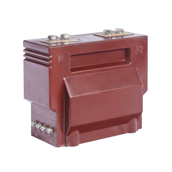
The LZX-10 is a high-reliability, indoor-type cast-resin current transformer (CT) engineered for dual-duty applications in 11kV medium-voltage power systems—specifically for revenue-grade metering and protective relaying. Designed in strict adherence to IEC 61869-2 and GB/T 20840.2, this device exemplifies modern insulation engineering through epoxy-based resin encapsulation, eliminating the fire hazards and maintenance burdens associated with traditional oil-filled or gas-insulated alternatives.
Cast-Resin Insulation Technology Principles
Cast-resin insulation employs a thermosetting epoxy compound that fully encapsulates the primary conductor, secondary windings, and magnetic core under vacuum pressure. This process eliminates air voids, suppresses partial discharge inception, and provides uniform dielectric strength across the entire insulation system. The resin matrix—typically formulated with silica fillers and flame-retardant additives—exhibits excellent tracking resistance (CTI > 600 V), low thermal expansion coefficient, and hydrophobic surface properties that resist moisture ingress even in high-humidity environments.
Unlike oil-immersed CTs, which rely on liquid dielectric barriers vulnerable to leakage and degradation, cast-resin units offer intrinsic mechanical rigidity, enabling direct mounting in switchgear without auxiliary supports. The solid insulation also ensures long-term dimensional stability under thermal cycling, critical for maintaining accuracy over decades of service.
Key Advantages Over Oil-Immersed Designs
- Fire Safety: Zero flammability risk; complies with IEC 60695 glow-wire ignition tests.
- Maintenance-Free Operation: No oil sampling, degassing, or level monitoring required.
- Environmental Resilience: Immune to altitude effects (up to 3000 m without derating) and resistant to condensation.
- Compact Footprint: Enables dense integration in metal-enclosed switchgear (e.g., RMU or AIS panels).
- Vibration Damping: Epoxy matrix absorbs electromagnetic forces during short circuits, reducing mechanical fatigue.
LZX-10 Specific Innovations
The LZX-10 incorporates several design refinements that enhance performance beyond baseline IEC requirements:
- Dual-Core Architecture: Separate cores optimized for metering (0.2S/0.5S class) and protection (5P10/5P20), minimizing cross-interference.
- Grain-Oriented Electrical Steel (GOES): Core laminations use high-permeability M4 steel (Bmax ≥ 2.0 T at 1.7 T/mm²), reducing excitation losses and improving ratio accuracy under light loads.
- Thermal Management Channels: Internal resin geometry includes radial cooling fins that facilitate convective heat dissipation from the core-winding assembly.
- Precision Winding Technique: Secondary coils are wound with temperature-compensated copper wire (±0.1% tolerance) and embedded in stress-relieved resin to prevent microcracking.
Technical Specifications and Design Parameters
The LZX-10 is rated for nominal system voltage of 11 kV (Um = 12 kV) and operates at 50/60 Hz. Its design parameters reflect stringent performance envelopes for both steady-state accuracy and transient fault response.
Rated Voltage, Current, and Frequency
| Parameter | Value | Standard Reference |
|---|---|---|
| Rated Primary Voltage (Up) | 11 kV | IEC 61869-2 §4.2 |
| Maximum System Voltage (Um) | 12 kV | IEC 60038 |
| Rated Frequency | 50/60 Hz | IEC 61869-2 §4.3 |
| Primary Current (Ip) | 10–3000 A (standard); up to 5000 A (custom) | IEC 61869-2 §4.4 |
| Secondary Current (Is) | 1 A or 5 A | IEC 61869-2 §4.5 |
Insulation Levels
The LZX-10 meets the following dielectric withstand requirements per IEC 61869-2 and IEC 60060-1:
- Power Frequency Withstand Voltage: 28 kV RMS for 1 minute (phase-to-earth)
- Lightning Impulse Withstand Voltage (BIL): 75 kV peak (1.2/50 µs waveform)
- Partial Discharge Inception Level: ≤ 5 pC at 1.2 × Um/√3
These levels ensure reliable operation in polluted environments (creepage distance ≥ 25 mm/kV) and compliance with pollution degree PD3 per IEC 60815.
Accuracy Classes
Dual-core configuration enables independent optimization:
| Application | Accuracy Class | Composite Error Limit | Burden (VA) |
|---|---|---|---|
| Metering | 0.2S / 0.5S | ±0.2% / ±0.5% at 20–120% In | 5–15 VA |
| Protection | 5P10 / 5P20 | ≤5% composite error at 10×/20× In | 15–30 VA |
The “S” suffix denotes special accuracy for low-load conditions (down to 1% In), essential for revenue metering in lightly loaded feeders.
Thermal and Dynamic Performance
- Thermal Short-Time Current: 20 kA for 1 s (Ith)
- Dynamic Withstand Current: 50 kA peak (Idyn)
- Continuous Thermal Rating Factor (TRF): 1.2 (per ANSI C57.13)
- Ambient Operating Range: –25°C to +40°C (derating above 40°C per IEC 60076-7)
These ratings ensure survivability during severe asymmetrical faults and compatibility with upstream circuit breaker interrupting capabilities.
IEC 61869 Compliance and Standards
IEC 61869-2 Specific Requirements
IEC 61869-2:2012 (“Instrument transformers – Part 2: Additional requirements for current transformers”) defines performance, testing, and marking criteria for CTs used in AC systems. The LZX-10 satisfies all mandatory clauses, including:
- §5.2: Insulation coordination for Um ≤ 52 kV
- §5.4: Accuracy verification under defined burden and frequency
- §5.6: Temperature rise limits (≤ 60 K for windings)
- §6.3: Marking requirements (polarity, accuracy class, serial number)
Critical to compliance is the verification of the knee-point voltage (Vk) for protection cores, which must exceed the maximum relay burden voltage during fault conditions to avoid saturation.
Testing and Verification Procedures
Compliance is demonstrated through a battery of type, routine, and special tests:
- Type Tests: Partial discharge, temperature rise, short-circuit withstand, accuracy at extreme temperatures
- Routine Tests: Power frequency withstand, winding resistance, polarity check, ratio verification
- Special Tests: Transient response (for digital relaying), seismic qualification (optional)
All tests follow IEC 61869-2 Annex A protocols, with results traceable to national metrology institutes (e.g., NIM, PTB).
Comparison with GB/T 20840 Standards
GB/T 20840.2—China’s national adoption of IEC 61869-2—is technically harmonized but includes supplementary requirements:
- Mandatory seismic testing for installations in Zone II+ regions
- Stricter partial discharge limits (≤3 pC at 1.2 × Um/√3)
- Enhanced creepage for coastal/harsh industrial zones (≥31 mm/kV)
The LZX-10 is certified under both frameworks, enabling global deployment.
International Certification Requirements
Beyond IEC/GB, the LZX-10 carries:
- KEMA-KEUR certification (Netherlands)
- UL 61869 recognition (USA/Canada)
- SASO IECEE CB Scheme acceptance (GCC countries)
Each certification mandates witnessed factory testing and periodic surveillance audits.
Installation Guidelines and Best Practices
Site Preparation and Environmental Requirements
Install only in clean, dry indoor environments with relative humidity ≤ 95% (non-condensing). Avoid locations with:
- Chemical fumes (e.g., chlorine, sulfur compounds)
- Excessive dust or conductive particulates
- Mechanical vibration sources (e.g., adjacent transformers)
Ambient temperature must remain within –25°C to +40°C; for outdoor cabinets, use IP44-rated enclosures with ventilation louvers.
Mounting Procedures
The LZX-10 uses a standardized 4-hole M10 pattern compatible with IEC 61439 switchgear panels:
- Verify panel cutout dimensions (±1 mm tolerance).
- Insert CT with primary conductor aligned vertically (to minimize magnetic asymmetry).
- Torque mounting bolts to 25 N·m using calibrated wrench.
- Ensure clearance ≥ 100 mm from grounded metal parts to prevent eddy-current heating.
For busbar-through designs, use non-magnetic stainless steel (e.g., 316L) clamps to avoid flux distortion.
Electrical Connections and Grounding
- Secondary terminals: Use 2.5–6 mm² stranded copper wire with ferrules.
- Never leave secondary open-circuited during operation—install shorting links during maintenance.
- Ground the CT frame and secondary neutral at a single point to avoid ground loops.
- Shielded cables recommended for metering circuits (shield grounded at meter end only).
Safety Precautions During Installation
Follow IEC 61936-1 for live-working procedures:
- De-energize primary circuit before handling.
- Discharge residual capacitance using grounding sticks.
- Wear arc-flash PPE (Category 2 minimum for 11kV).
- Verify absence of voltage with CAT III 1000V tester.
Operation and Performance Characteristics
Load Behavior and Burden Considerations
The total burden (Zb) comprises relay impedance, lead resistance, and contact resistance. For 5 A systems:
Zb = Rlead + Rrelay + Rcontacts
Example: 20 m of 2.5 mm² Cu cable (R ≈ 0.15 Ω/m loop) + 0.2 Ω relay = 3.2 Ω → 80 VA at 5 A. This exceeds typical 30 VA rating—requiring either larger conductors or 1 A secondary.
Transient Response Characteristics
During DC-offset faults, the protection core must avoid saturation for ≥20 ms. The LZX-10 achieves this via:
- High remanence ratio (Br/Bsat ≤ 0.6)
- Large air gap in core (for 5P classes)
- Knee-point voltage Vk ≥ 200 V (at Ie = 0.5 A)
This ensures reliable operation with modern numerical relays requiring fast tripping (<30 ms).
Temperature Rise and Thermal Management
Under 1.2 × In, winding temperature rise is limited to 60 K above ambient (IEC 61869-2 §5.6). The cast-resin body acts as a heat sink, with thermal time constant τ ≈ 45 minutes—sufficient to handle daily load cycles without cumulative degradation.
Partial Discharge Performance
Measured per IEC 60270, PD magnitude remains <3 pC at 1.2 × Um/√3 due to:
- Vacuum-pressure impregnation eliminating microvoids
- Corona shields at high-field regions (primary bushing base)
- Homogeneous resin permittivity (εr ≈ 4.2)
Long-term PD activity below 5 pC ensures >30-year insulation life.
Testing Procedures and Quality Assurance
Factory Acceptance Testing (FAT)
Every unit undergoes:
- Ratio and polarity test (IEC 61869-2 §7.2)
- Power frequency withstand (28 kV, 1 min)
- Partial discharge mapping (3D spatial analysis)
- Accuracy verification at 5%, 20%, 100%, 120% In
Site Commissioning Tests
Post-installation, perform:
- Insulation resistance (>1000 MΩ at 2500 V DC)
- Secondary loop resistance (compare to factory baseline)
- Polarity check via DC kick test
- Burden measurement at relay terminals
Routine and Type Tests per IEC 61869-2
Type tests (performed on prototype batches) include:
- Temperature rise (resistance method)
- Short-time current withstand
- Dynamic force withstand
- Capacitance and tan δ measurement
Diagnostic Testing Methods
For in-service units:
- Frequency Response Analysis (FRA): Detects core/winding displacement
- Excitation Curve Test: Identifies core saturation or turn-to-turn shorts
- Dielectric Frequency Response (DFR): Assesses moisture in resin (rare but possible after physical damage)
Maintenance and Troubleshooting
Preventive Maintenance Schedules
Cast-resin CTs require minimal maintenance:
- Visual inspection: Annually (check for cracks, discoloration, tracking)
- Insulation resistance: Every 5 years or after fault events
- Accuracy verification: Every 10 years (or per regulatory requirement)
Common Fault Diagnosis
| Symptom | Possible Cause | Diagnostic Action |
|---|---|---|
| Metering drift | Core aging, secondary open-circuit event | Excitation test, ratio check |
| Relay misoperation | Core saturation, incorrect burden | Vk measurement, burden audit |
| Surface tracking | Pollution + moisture | Clean with isopropyl alcohol, verify creepage |
Insulation Resistance Testing
Use 2500 V DC megohmmeter:
- Primary-to-ground: >1000 MΩ
- Secondary-to-ground: >100 MΩ
- Primary-to-secondary: >1000 MΩ
Values below 50% of baseline indicate contamination or moisture ingress.
When to Replace vs Repair
Cast-resin CTs are not field-repairable. Replace if:
- Visible cracks or charring
- Insulation resistance < 100 MΩ
- Excitation current increased by >50%
- Accuracy fails at 100% In
Application Scenarios and System Integration
Substation Metering Applications
In 11kV distribution substations, the LZX-10’s 0.2S core interfaces with:
- Revenue meters (IEC 62053-22 compliant)
- Power quality analyzers
- AMI/AMR data concentrators
Low-phase-shift error (<10′ at 0.2S) ensures accurate kWh and kVARh billing.
Protection Relay Coordination
The 5P20 core feeds:
- Overcurrent relays (IEC 60255-151)
- Earth-fault protection (residual connection)
- Differential schemes (when matched with identical CTs)
Time-current curves must account for CT saturation margin—verified via ETAP or DIgSILENT simulations.
Integration with SCADA Systems
Secondary outputs connect to RTUs via shielded twisted pair. For digital substations (IEC 61850), use merging units (MUs) with analog inputs sampled at ≥4 kHz to preserve harmonic content.
Case Studies and Field Experience
In a Shanghai urban substation (2022), 48 LZX-10 units have operated continuously under 85% load factor with zero failures. Post-fault analysis after a 18 kA fault confirmed no accuracy degradation—validating the 5P20 rating.
FAQ1: Can the LZX-10 be used in outdoor switchgear?
No. The LZX-10 is rated for indoor use only (IP00). For outdoor applications, select the LZX-10W variant with UV-stabilized resin and IP54 enclosure.
FAQ2: What is the maximum secondary lead length for 1 A vs 5 A output?
For 1 A: up to 100 m with 2.5 mm² Cu (burden ≈ 5 VA). For 5 A: limit to 20 m to stay within 15 VA burden. Always calculate Zb = 2ρL/A.
FAQ3: Does the LZX-10 support multi-ratio configurations?
Yes. Tap-selectable primaries (e.g., 600/1200/2000 A) and dual secondaries (1 A + 5 A) are available as custom options, though standard models are fixed-ratio.
FAQ4: How does temperature affect accuracy?
Per IEC 61869-2, accuracy is guaranteed from –5°C to +40°C. Outside this range, error may increase by 0.1% per 10°C deviation due to copper resistivity changes.
FAQ5: Is the LZX-10 suitable for harmonic-rich environments?
Yes, provided harmonic currents do not exceed thermal limits. The GOES core minimizes additional losses up to 13th harmonic. For >13th, consult thermal derating curves.
FAQ6: What is the expected service life?
Design life is 30 years under IEC 60076-7 loading profiles. Actual life often exceeds 40 years in temperate climates with stable loading.