Article Content
ZZW-35 11kV Cast-Resin Current Transformer for Substation Metering and Protection – IEC 61869-2 Certified
Introduction to the ZZW-35 Current Transformer
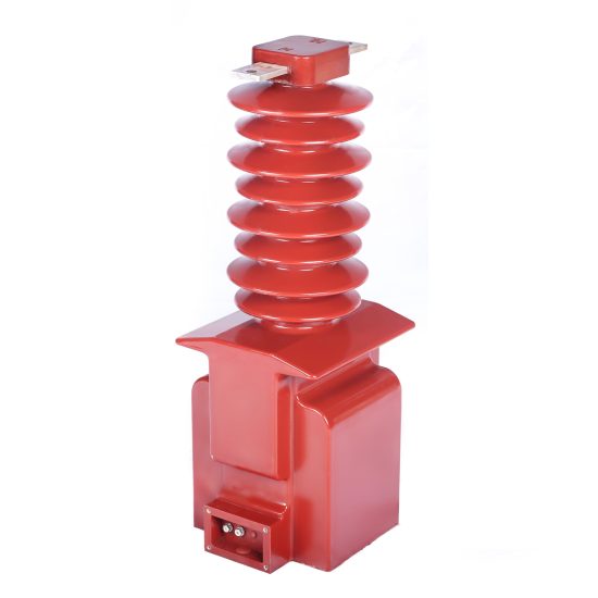
The ZZW-35 is a high-reliability, cast-resin insulated current transformer (CT) engineered for precision metering and robust protection functions in 11kV (IEC standard) or 10kV (domestic equivalent) medium-voltage power systems. Designed in strict accordance with IEC 61869-2 and GB/T 20840.2, this instrument transformer leverages vacuum pressure impregnation (VPI) epoxy resin technology to deliver superior dielectric performance, environmental resilience, and long-term operational stability without the fire hazards or maintenance demands associated with oil-filled alternatives.
Cast-resin insulation involves encapsulating the magnetic core and windings in a solid epoxy matrix under controlled vacuum and pressure conditions. This process eliminates air voids, moisture ingress pathways, and partial discharge risks—critical factors in ensuring consistent performance across temperature cycles and over decades of service. The resulting monolithic structure provides excellent mechanical strength, resistance to tracking and erosion, and immunity to UV degradation, making the ZZW-35 suitable for both indoor switchgear and outdoor substation installations.
Compared to traditional oil-immersed CTs, the ZZW-35 offers significant advantages: zero risk of oil leakage or flammability, reduced lifecycle costs due to minimal maintenance, compact physical footprint, and faster commissioning. Its non-hygroscopic nature ensures stable insulation properties even in high-humidity coastal or industrial environments. These attributes make it ideal for modern smart grids, renewable integration points, and urban substations where safety, space efficiency, and reliability are paramount.
Operating Principle and Core Design
The ZZW-35 operates on the fundamental principle of electromagnetic induction. Primary current flowing through the central conductor induces a proportional secondary current in the wound secondary coil, scaled by the turns ratio (e.g., 100/5 A or 300/1 A). The core is constructed from grain-oriented electrical steel (GOES), specifically selected for its low hysteresis loss, high permeability, and minimal remanence—essential for maintaining accuracy under both steady-state and transient fault conditions. The GOES laminations are annealed and precisely stacked to minimize eddy current losses, ensuring thermal stability during continuous operation at rated load and short-time thermal withstand during fault events.
Advantages Over Oil-Immersed Designs
Oil-immersed CTs require periodic oil sampling, gasket replacement, and leak monitoring, introducing operational complexity and environmental liability. In contrast, the ZZW-35’s solid cast-resin construction eliminates these concerns. It achieves a partial discharge inception voltage exceeding 1.2 times the highest system voltage (Um = 12 kV), per IEC 61869-2 Clause 7.4. The absence of liquid insulation also removes explosion risks in confined spaces, aligning with modern safety codes such as IEC 61439 for switchgear assemblies. Additionally, the thermal time constant of epoxy resin allows faster heat dissipation than oil, supporting higher short-circuit current ratings (typically 20–40 kA for 1–3 seconds).
Typical Deployment Scenarios
The ZZW-35 is commonly deployed in 11kV ring main units (RMUs), gas-insulated switchgear (GIS), and air-insulated substations serving commercial complexes, industrial plants, and utility distribution feeders. It supports dual secondary windings—one optimized for 0.2S or 0.5S class metering (per IEC 61869-2 Table 102), the other for 5P10 or 5P20 protection accuracy. This dual-function capability reduces equipment count and simplifies secondary wiring. In solar or wind farm collector substations, the ZZW-35 provides accurate revenue metering while reliably tripping circuit breakers during ground faults or phase imbalances, thanks to its linear response up to 20× rated current.
Technical Specifications
The ZZW-35 is engineered to meet stringent electrical, thermal, and mechanical requirements for medium-voltage applications. Below is a comprehensive specification table aligned with IEC 61869-2 and GB/T 20840.2:
| Parameter | Value |
|---|---|
| Rated System Voltage (IEC) | 11 kV |
| Rated System Voltage (Domestic) | 10 kV |
| Highest Voltage for Equipment (Um) | 12 kV |
| Primary Current Ratings | 50 A to 3000 A (standard); custom up to 4000 A |
| Secondary Current | 1 A or 5 A |
| Accuracy Classes | Metering: 0.2S, 0.5S; Protection: 5P10, 5P20 |
| Rated Burden (VA) | 5, 10, 15, 30 VA (per winding) |
| Short-Time Thermal Current (Ith) | 20 kA/1s, 25 kA/1s, or 40 kA/3s (model-dependent) |
| Dynamic Withstand Current (Idyn) | 50 kA peak |
| Power Frequency Withstand Voltage | 28 kV rms / 1 min (phase-to-earth) |
| Lightning Impulse Withstand Voltage | 75 kV peak (1.2/50 μs) |
| Insulation Material | VPI Epoxy Resin with Al₂O₃ filler |
| Core Material | GOES (Grain-Oriented Electrical Steel), 0.3 mm thickness |
| Ambient Temperature Range | -40°C to +40°C |
| Altitude Limit | ≤ 1000 m (derating required above) |
| Relative Humidity | Up to 95% non-condensing |
| IP Rating | IP00 (for switchgear mounting); IP2X with optional cover |
Standard Service Conditions
The ZZW-35 is rated for normal service conditions as defined in IEC 61869-2 Clause 5.1: ambient temperature between -40°C and +40°C, daily average not exceeding +35°C. Relative humidity may reach 95% provided condensation does not occur on the surface—a condition ensured by the hydrophobic nature of the epoxy resin. Installation altitude must not exceed 1000 meters above sea level; for sites between 1000–3000 m, the power frequency withstand voltage must be derated by 1% per 100 m increment. The transformer is designed for continuous operation at 1.2× rated primary current without exceeding temperature rise limits (≤ 60 K for resin, ≤ 50 K for windings per IEC 60076-2).
Electrical Performance Parameters
Accuracy compliance is verified at 1%, 5%, 20%, 100%, and 120% of rated primary current for metering classes, and at 100% and rated accuracy limit factor (e.g., 10× or 20×) for protection classes. Composite error for 5P20 must not exceed 5% at 20× rated current with burden at rated VA. Phase displacement is limited to ±10 minutes for 0.2S class at 100% load. The secondary winding DC resistance tolerance is ±5% of nominal value, critical for burden calculation in relay coordination studies.
Typical Applications
The ZZW-35 serves as a cornerstone component in diverse power infrastructure projects requiring precise current measurement and dependable fault detection.
Substation Secondary Metering Systems
In utility-owned 11kV/0.4kV distribution substations, the ZZW-35’s 0.2S-class secondary winding interfaces directly with revenue-grade kWh meters and SCADA RTUs. Its low phase error (< ±5 minutes at 100% load) ensures billing accuracy compliant with EN 50470-1 and DLMS/COSEM protocols. For example, in a 2 MVA urban substation feeding commercial loads, two ZZW-35 units (one per phase) provide three-phase current data to an AMI head-end system, enabling real-time load profiling and theft detection. The cast-resin body resists pollution-induced flashovers common in industrial zones with airborne conductive dust.
Industrial Power Distribution Networks
Heavy industries—such as cement plants, steel mills, and data centers—deploy the ZZW-35 on 11kV motor control centers (MCCs) and feeder breakers. Here, the 5P20 protection winding drives numerical relays (e.g., Siemens 7SJ62) that detect phase-to-phase or earth faults within 20 ms. The CT’s high saturation point (Vk ≥ 500 V for 5P20 at 30 VA burden) prevents maloperation during motor inrush currents, which can reach 6–8× full-load current for 100–500 ms. Its compact dimensions (e.g., 180 mm height × 120 mm width) allow retrofitting into legacy switchgear without panel modifications.
Renewable Energy Integration Points
Solar photovoltaic (PV) farms and onshore wind clusters use the ZZW-35 at the 11kV collector substation output. During grid faults, the CT must accurately reproduce asymmetric fault currents containing DC offset—up to 100% of AC magnitude for 150 ms. The GOES core’s low remanence ensures rapid demagnetization post-fault, avoiding residual flux that could saturate the core during subsequent events. In a 20 MW solar plant, ZZW-35 units feed both revenue meters (for PPA compliance) and distance relays protecting the interconnection transformer, demonstrating dual-role efficiency.
Rural and Suburban Distribution Feeders
For rural electrification projects, the ZZW-35’s outdoor durability is critical. Mounted on pole-top reclosers or pad-mounted transformers, it withstands temperature swings from -30°C (winter) to +45°C (summer desert conditions). Its UV-stabilized resin prevents surface cracking, while hydrophobicity sheds rain and snow. In China’s “New Rural Grid” initiative, ZZW-35 CTs with 10kV domestic rating support state-grid AMR systems, transmitting hourly consumption data via GPRS modules integrated into the terminal box.
Urban Underground Networks
In cities with space-constrained underground substations (e.g., subway traction power or hospital backup systems), the ZZW-35’s fire-safe design meets IEC 60332-1 flame retardancy standards. Unlike oil-filled units, it emits no toxic fumes during internal arcing, enhancing personnel safety in enclosed vaults. Its low partial discharge (< 5 pC at 1.2 Um/√3) ensures compatibility with sensitive electronic protection relays in critical infrastructure.
Compliance with International Standards
The ZZW-35 is certified to IEC 61869-2:2012 (“Instrument transformers – Part 2: Additional requirements for current transformers”) and fully harmonized with China’s GB/T 20840.2-2014. This dual compliance enables global deployment while meeting local regulatory mandates.
IEC 61869-2 Certification Requirements
IEC 61869-2 defines type tests, routine tests, and special tests for CTs. The ZZW-35 undergoes all mandatory type tests: temperature rise (Clause 7.2), short-circuit withstand (Clause 7.3), insulation (Clause 7.4), accuracy (Clause 7.5), and radio interference voltage (Clause 7.6). Notably, the standard requires verification of accuracy at 1% of rated current for 0.2S class—a stringent test passed by the ZZW-35 due to its low-core-loss GOES material. The certification includes a test report from an ISO/IEC 17025-accredited lab, documenting composite error, ratio error, and phase displacement across the full current range.
Alignment with GB/T 20840.2
GB/T 20840.2 mirrors IEC 61869-2 but adds China-specific requirements: mandatory lightning impulse test at 75 kV (vs. IEC’s 75 kV for Um=12 kV), and stricter partial discharge limits (< 10 pC at 1.2 Um/√3). The ZZW-35 exceeds both, achieving < 5 pC in factory tests. Additionally, GB/T 20840.2 mandates a 1-minute power frequency test at 28 kV—identical to IEC—ensuring interchangeability in Sino-foreign joint ventures. Documentation includes bilingual (Chinese/English) test certificates issued by CEPREI or TÜV Rheinland China.
Key Differences Between IEC and Domestic Standards
While IEC 61869-2 permits 10% tolerance on rated burden, GB/T 20840.2 requires ±5%. The ZZW-35 is manufactured to the tighter GB tolerance, ensuring backward compatibility. Another divergence: IEC allows 5P10 as minimum protection class, whereas Chinese grid codes often specify 5P20 for 110 kV down to 10 kV feeders. The ZZW-35 offers both options. Environmental testing also differs—I EC references IEC 60068 for climate, while GB uses GB/T 2423—but the ZZW-35 passes both (-40°C cold start, 85°C damp heat).
On-Site Testing Procedures
Post-installation verification ensures the ZZW-35 performs within specifications before energization. All tests follow IEC 61869-2 Annex D and IEEE C57.13.2 guidelines.
Insulation Resistance Test
Using a 2500 V DC megohmmeter, measure insulation resistance between primary conductor and secondary windings/ground. Acceptance criterion: ≥ 1000 MΩ at 20°C. Correct for temperature using R₂₀ = Rₜ × 2^((20−t)/10). Low readings (< 100 MΩ) indicate moisture ingress or resin cracking—requiring drying or replacement. Perform before and after power frequency withstand test to detect insulation degradation.
Turns Ratio Test
Apply low-voltage AC (5–10 V) to the secondary winding and measure induced primary voltage (open-circuit). Calculate actual ratio = V_secondary / V_primary. Compare to nameplate; tolerance must be within ±0.2% for metering classes, ±0.5% for protection. Modern ratio testers (e.g., Omicron CT Analyzer) automate this with < 0.05% uncertainty. Deviations >1% suggest inter-turn shorts or incorrect tap selection.
Polarity Test
Verify reducing polarity per IEC 61869-2 Figure 101: connect DC source (+) to P1, (−) to P2; connect galvanometer (+) to S1, (−) to S2. Momentary closure should show positive kick. Incorrect polarity causes wattmeter reversal or relay misoperation. Digital multimeters with diode-test mode can substitute for galvanometers. Polarity errors are common during multi-ratio CT wiring and must be corrected before commissioning.
Power Frequency Withstand Voltage Test
Apply 28 kV rms at 50 Hz between primary and grounded secondary/enclosure for 1 minute. Use a calibrated test transformer with overcurrent trip (≤ 100 mA). No flashover or disruptive discharge is permitted. Ramp voltage at 2 kV/s to avoid transient overstress. This test validates insulation integrity after transport vibration. If failed, inspect for resin voids or contamination on bushing surfaces.
Short-Circuit Test (for CTs)
Unlike VTs, CTs require short-circuit validation. Energize primary at 10–20% rated current with secondary shorted. Measure secondary current; ratio error must comply with accuracy class. Then, simulate fault by injecting 10× rated current for 1 second (using portable test set). Verify no excessive heating or mechanical deformation. Post-test, recheck insulation resistance to confirm no thermal damage to resin.
Preventive Maintenance Guide
Although cast-resin CTs are largely maintenance-free, periodic checks extend service life beyond 30 years.
Annual Visual and Electrical Inspection
Inspect for surface cracks, tracking marks, or discoloration on the resin body—indicative of partial discharge or UV degradation. Clean with dry cloth; never use solvents. Check terminal tightness (torque: 2.5 N·m for M6 screws). Perform insulation resistance and ratio tests annually in harsh environments (coastal, industrial). Record trends; a 20% drop in insulation resistance warrants investigation. Ensure secondary circuits remain shorted when disconnected to prevent dangerous open-circuit voltages.
Five-Year Comprehensive Maintenance
Every 60 months, conduct full IEC 61869-2 routine tests: accuracy verification at multiple points, partial discharge measurement (< 10 pC at 1.2 Um/√3), and dynamic withstand simulation. Use a CT analyzer to plot excitation curves—saturation voltage (Vk) should match factory data within ±5%. Replace terminal box gaskets if hardened. In seismic zones, verify mounting bolt torque (8 N·m) to prevent resonance-induced fatigue.
Categories
Blog
Recommended Posts


