Article Content
INE-2 11kV Cast-Resin Voltage Transformer for Metering and Protection – IEC 61869-3 Certified
Introduction to the INE-2 Voltage Transformer
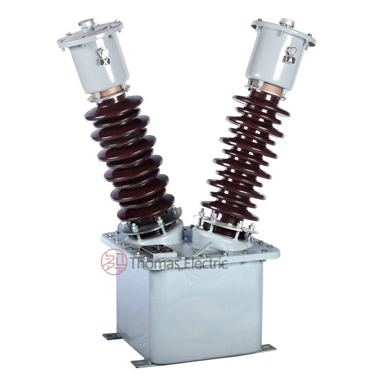
The INE-2 is a single-phase, indoor/outdoor-rated cast-resin voltage transformer (VT) engineered for high-reliability metering and protective relaying applications in medium-voltage distribution networks operating at 11kV (IEC standard) or 10kV (domestic Chinese system). Designed in strict accordance with IEC 61869-3 and GB/T 20840.3, this instrument transformer leverages advanced vacuum pressure impregnation (VPI) epoxy resin technology to provide superior dielectric strength, environmental resilience, and long-term operational stability.
Operating Principle of Cast-Resin Insulation
Cast-resin insulation in the INE-2 VT involves encapsulating the primary and secondary windings—wound on a grain-oriented electrical steel (GOES) core—within a solid matrix of thermosetting epoxy resin under vacuum and pressure. This process eliminates air voids and moisture ingress pathways, ensuring uniform electric field distribution and preventing partial discharge even under transient overvoltages. The resin’s high tracking resistance (>600 V according to IEC 60587) and hydrophobic surface properties make it ideal for humid or polluted environments. Unlike oil-filled units, the solid insulation eliminates fire hazards, leakage risks, and maintenance-intensive oil sampling, aligning with modern substation safety and sustainability requirements.
Advantages Over Oil-Immersed Designs
Compared to traditional oil-immersed VTs, the INE-2 offers significant operational and lifecycle benefits. Its dry-type construction eliminates flammability concerns, enabling safe installation in confined spaces such as indoor switchgear rooms or commercial buildings. The absence of oil also removes the need for conservator tanks, breather systems, and periodic dielectric testing of insulating fluid. Furthermore, the thermal stability of epoxy resin allows consistent performance across ambient temperatures from -40°C to +40°C, with no degradation in accuracy due to thermal expansion mismatches. Weight reduction (typically 30–40% lighter than equivalent oil units) simplifies handling and mounting, while the monolithic structure resists mechanical vibration and seismic loads up to 0.5g.
Typical Applications Overview
The INE-2 is deployed across utility substations, industrial plants, renewable energy facilities, and urban distribution networks where precision voltage measurement and reliable fault detection are critical. It interfaces directly with revenue-class energy meters (Class 0.2 or 0.5S), digital protective relays (e.g., distance, overvoltage, undervoltage), and SCADA systems. Its dual-winding configuration supports simultaneous metering and protection outputs, eliminating the need for separate transformers. In ring-main units (RMUs) and compact secondary substations, the INE-2’s compact footprint and robust insulation enable space-efficient integration without compromising safety margins.
Technical Specifications
The INE-2 voltage transformer is engineered to deliver precise voltage transformation under defined service conditions while maintaining compliance with international and domestic standards. Below is a comprehensive specification table followed by detailed environmental and operational parameters.
| Parameter | Value |
|---|---|
| System Voltage (IEC) | 11 kV |
| System Voltage (Domestic) | 10 kV |
| Primary Voltage | 11 / √3 kV (phase-to-earth) |
| Secondary Voltages | 100 / √3 V (metering), 100 / √3 V (protection) |
| Voltage Ratio | (11000 / √3) : (100 / √3) = 110 : 1 |
| Accuracy Class (Metering) | 0.2 or 0.5 (per IEC 61869-3) |
| Accuracy Class (Protection) | 3P or 6P |
| Rated Output (Metering) | 30 VA (Class 0.2), 50 VA (Class 0.5) |
| Rated Output (Protection) | 100 VA (Class 3P), 150 VA (Class 6P) |
| Insulation Level (LI/AC) | 75 kV / 28 kV (1 min, 50 Hz) |
| Short-Time Thermal Withstand | 1 s at 16 kA (symmetrical) |
| Core Material | Grain-Oriented Electrical Steel (GOES), 0.27 mm thickness |
| Insulation System | VPI Epoxy Resin, UL 94 V-0 rated |
| Ambient Temperature Range | -40°C to +40°C |
| Altitude Limit | ≤ 1000 m above sea level (derating required >1000 m) |
| Relative Humidity | Up to 95% non-condensing |
Standard Service Conditions
The INE-2 is rated for continuous operation under standard service conditions as defined in IEC 61869-3 Clause 5. These include an ambient temperature range of -40°C to +40°C, with a 24-hour average not exceeding +35°C. Relative humidity may reach 95% provided condensation does not occur on the housing. Installation altitude must not exceed 1000 meters; for altitudes between 1000 m and 3000 m, the power frequency withstand voltage must be reduced by 1% per 100 m above 1000 m. The transformer assumes a symmetrical three-phase system with balanced loading and nominal frequency of 50 Hz (±0.5 Hz). Transient overvoltages up to 1.2 × Ur are permissible for durations ≤ 1 second without damage.
Electrical Performance Tolerances
Voltage error and phase displacement are tightly controlled per accuracy class. For Class 0.2 metering windings, voltage error must not exceed ±0.2% and phase displacement ≤ ±10 minutes at 25–100% of rated burden. Protection windings (Class 3P) permit ±3% voltage error and ±120 minutes phase shift at 100% burden. Ratio error tolerance during turns ratio testing is ±0.1%. Burden must be purely resistive-inductive (power factor 0.8 lagging) unless otherwise specified. Open-circuit secondary voltage must remain within ±0.5% of nominal under no-load conditions at rated primary voltage.
Typical Applications
The INE-2 voltage transformer serves as a foundational component in modern power systems requiring accurate voltage sensing for billing, control, and fault isolation. Its dual-secondary design enables concurrent use in revenue metering and protective relaying circuits without cross-interference.
Substation Secondary Metering
In 11kV/0.4kV distribution substations, the INE-2 provides scaled-down voltage signals to Class 0.2S static energy meters for utility billing. The metering secondary (100/√3 V) connects directly to the meter’s voltage input terminals, while the protection winding feeds overvoltage relays (e.g., ANSI 59) or undervoltage elements (ANSI 27). The transformer’s low phase displacement ensures minimal reactive energy measurement error, critical for power factor correction and tariff compliance. In smart grid deployments, the INE-2 integrates with IEC 61850-compliant merging units for sampled value transmission.
Industrial Power Distribution
Large manufacturing facilities often operate 10kV/11kV internal distribution networks fed from utility feeders. Here, the INE-2 monitors bus voltage for motor protection schemes (e.g., loss-of-voltage tripping for synchronous motors) and synchronism checks during generator paralleling. Its high short-circuit withstand capability (16 kA for 1 s) ensures survival during downstream faults, maintaining relay supervision integrity. The cast-resin housing resists chemical fumes and dust common in industrial environments, eliminating the need for sealed enclosures.
Renewable Energy Integration
Solar PV and wind farms frequently connect to 11kV collection grids. The INE-2 enables anti-islanding protection by detecting voltage deviations outside EN 50160 limits (e.g., >1.1 × Un or <0.85 × Un). It also supports reactive power control (Q(V) droop) by providing real-time voltage feedback to inverters. In microgrids, the VT facilitates seamless transition between grid-connected and islanded modes through precise voltage magnitude and angle measurement. Its immunity to DC offset makes it suitable for inverter-based resource interconnection.
Rural and Suburban Distribution Networks
In remote or lightly loaded areas, the INE-2 is mounted on pole-top platforms or pad-mounted switchgear to supply voltage signals for automatic voltage regulators (AVRs) and capacitor bank controllers. Its maintenance-free design reduces outage frequency in hard-to-access locations. The transformer’s high insulation coordination margin (BIL 75 kV vs. system LI 75 kV) protects against lightning-induced surges common in overhead line segments. Dual secondaries allow one output for local telemetry and another for centralized SCADA polling.
Compliance with International Standards
The INE-2 voltage transformer is certified to meet the stringent requirements of both global and national standards, ensuring interoperability, safety, and performance consistency across diverse grid environments.
IEC 61869-3 Compliance Details
IEC 61869-3:2011 specifies general requirements for electromagnetic voltage transformers, including definitions, ratings, tests, and marking. The INE-2 complies fully with Clauses 4–10, covering rated values, accuracy classes, temperature rise limits (<60 K for windings), and type tests. Key verifications include power frequency withstand (28 kV rms for 1 min), lightning impulse (75 kV peak, 1.2/50 µs waveform), and partial discharge levels (<10 pC at 1.2 × Ur/√3). The standard mandates that voltage error and phase displacement be verified at 25%, 50%, 100%, and 120% of rated burden—tests routinely performed during factory acceptance.
GB/T 20840.3 Alignment
GB/T 20840.3-2013 is the Chinese national adoption of IEC 61869-3, with minor modifications reflecting domestic grid practices. The INE-2 meets all GB-specific requirements, including the use of 10kV as the nominal system voltage (vs. 11kV in IEC) and acceptance of Class 0.2S for revenue metering. Chinese standards also emphasize seismic performance (tested per GB/T 13540), which the INE-2 satisfies via reinforced core clamping and resin anchoring. Marking includes both IEC and GB voltage ratios to facilitate dual-market deployment.
Testing and Certification Requirements
Certification requires successful completion of routine tests (100% production), type tests (prototype validation), and special tests (on request). Routine tests include polarity check, turns ratio verification, and insulation resistance (>1000 MΩ at 2500 V DC). Type tests encompass temperature rise, short-circuit withstand, and accuracy verification across burden ranges. Third-party certification by accredited labs (e.g., KEMA, CESI, or China Electric Power Research Institute) confirms compliance. Each unit ships with a test report traceable to ISO/IEC 17025 standards.
On-Site Testing Procedures
Post-installation verification ensures the INE-2 performs within specifications before energization. All tests follow IEC 60060-1 and IEEE C57.13 guidelines.
Insulation Resistance Test
Using a 2500 V DC megohmmeter, measure insulation resistance between primary winding and ground, secondary windings and ground, and primary-to-secondary. Acceptance criterion: ≥1000 MΩ at 20°C. Correct for temperature using RT = R20 × 2(20−T)/10. Low readings indicate moisture ingress or resin cracking—requiring drying or replacement.
Turns Ratio Test
Apply 100–200 V AC to the primary and measure secondary voltage. Calculate ratio as Vp/Vs. Tolerance: ±0.1% of nominal ratio (110:1). Use a dedicated ratio tester (e.g., Omicron CT Analyzer) for automated comparison. Deviations >0.2% suggest turn-to-turn shorts or incorrect tapping.
Polarity Test
Verify reducing polarity per IEC 61869-3 Figure 3. Connect a 6–12 V battery momentarily across primary terminals (H1+, H2−). Observe secondary voltage spike on a DC voltmeter connected to X1 (+) and X2 (−). A positive deflection confirms correct polarity. Incorrect polarity causes 180° phase reversal, leading to metering errors or relay misoperation.
Power Frequency Withstand Voltage Test
Apply 28 kV rms at 50 Hz between primary and grounded tank/secondary for 1 minute. Secondary windings are shorted and grounded. No flashover or breakdown permitted. Ramp voltage at ≤1 kV/s. This test validates insulation integrity after transport and installation stresses.
Open-Circuit Test
With secondary open, apply rated primary voltage (11/√3 kV) and measure excitation current and secondary voltage. Excitation current should be <0.5% of rated primary current. Secondary voltage must be within ±0.5% of 100/√3 V. Elevated excitation indicates core saturation or shorted turns.
Preventive Maintenance Guide
Although cast-resin VTs are largely maintenance-free, periodic inspection extends service life and prevents unexpected failures.
Periodic Inspection Protocol
Conduct visual and electrical checks annually. Inspect for surface tracking, cracks, or discoloration on the resin housing. Clean with dry cloth or mild detergent—never solvents. Verify terminal tightness (torque: 15 N·m for M8 bolts). Measure insulation resistance and compare to baseline. Check secondary wiring for loose connections or corrosion. Record all findings in asset management logs.
Maintenance Intervals and Fault Diagnosis
Replace silica gel breathers (if fitted on terminal boxes) every 2 years. Perform full electrical retesting every 5 years or after major system faults. Common failure modes include: (1) Partial discharge due to voids—detected via ultrasonic sensors; (2) Secondary winding open-circuit—causing dangerous overvoltage; (3) Core grounding faults—identified by elevated excitation current. If secondary voltage drops >5% under load, suspect internal degradation.
| Interval | Action |
|---|---|
| Annually | Visual inspection, IR scan, insulation resistance |
| Every 3 Years | Terminal torque verification, burden check |
| Every 5 Years | Full accuracy test, ratio verification, PD measurement |
| After Fault | Withstand test, open-circuit test, visual crack inspection |
Conclusion
The INE-2 11kV cast-resin voltage transformer represents a benchmark in reliability, accuracy, and compliance for modern power systems. By leveraging VPI epoxy resin encapsulation and GOES core technology, it delivers stable performance across extreme environmental conditions while eliminating the fire and environmental hazards associated with oil-filled alternatives. Its dual-secondary architecture supports simultaneous metering (Class 0.2/0.5) and protection (Class 3P/6P) functions with minimal phase displacement, ensuring precise energy billing and dependable fault detection. Full adherence to IEC 61869-3 and GB/T 20840.3 guarantees interoperability in global and domestic grids alike. With a design life of 25–30 years and minimal maintenance requirements, the INE-2 reduces total cost of ownership while enhancing grid resilience. Its robust insulation coordination (75 kV BIL) and short-circuit withstand capability (16 kA/1s) make it suitable for the most demanding utility and industrial applications. As distribution networks evolve toward digitalization and distributed generation, the INE-2 provides the foundational voltage sensing accuracy required for advanced grid management and protection strategies.