Article Content
Introduction to the RZL-10 Current Transformer
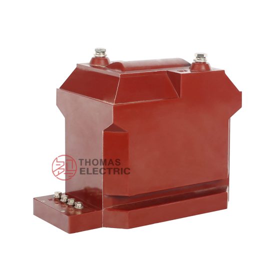
The RZL-10 is a high-precision, cast-resin insulated current transformer (CT) rated for 11 kV systems, specifically engineered for dual-service applications in electrical energy metering and protective relaying within medium-voltage (MV) substations. Unlike legacy oil-immersed or dry-type air-insulated CTs, the RZL-10 leverages advanced epoxy resin encapsulation technology to deliver superior dielectric integrity, mechanical robustness, and long-term operational stability under demanding environmental and electrical stress conditions.
Cast-Resin Insulation Technology Principles
Cast-resin insulation involves vacuum pressure impregnation (VPI) of high-purity cycloaliphatic epoxy resins around precision-wound primary and secondary windings, followed by controlled thermal curing. This process eliminates voids and microcavities that could serve as initiation sites for partial discharges (PD). The resulting monolithic structure provides:
- Homogeneous dielectric distribution with permittivity (εr) ≈ 3.5–4.0
- High tracking resistance (>600 V in CTI tests per IEC 60112)
- Excellent thermal conductivity (~0.8 W/m·K) enabling efficient heat dissipation
- Inherent hydrophobicity and resistance to surface contamination
Critical to performance is the use of low-viscosity, halogen-free resins with optimized filler loading (typically silica-based), which minimizes thermal expansion mismatch between copper conductors and the insulating matrix—thereby reducing mechanical stress during thermal cycling.
Key Advantages over Oil-Immersed Designs
Compared to traditional oil-filled CTs, the RZL-10’s solid insulation offers distinct engineering benefits:
- No fire hazard: Eliminates flammable insulating oil, enhancing safety in indoor switchgear rooms and urban substations.
- Maintenance-free operation: No oil sampling, degassing, or leakage monitoring required.
- Reduced footprint: Higher dielectric strength of epoxy resin allows for more compact core-winding geometry.
- Environmental resilience: Immune to oil degradation from UV exposure, oxidation, or moisture ingress.
- Lower lifecycle cost: Absence of periodic oil testing and containment infrastructure reduces OPEX.
RZL-10 Specific Innovations
The RZL-10 incorporates several design refinements beyond baseline cast-resin CTs:
- Dual-core configuration (metering + protection) in a single housing with independent secondary windings
- Grain-oriented electrical steel (GOES) cores with flux density optimized for low excitation error (<0.1% at 5 A burden)
- Laser-trimmed secondary terminals with silver-plated contacts to minimize contact resistance
- Integrated corona shields at high-voltage terminations to suppress field enhancement
- UV-stabilized outer resin layer for outdoor-rated variants (IP54 enclosure)
Technical Specifications and Design Parameters
The RZL-10 is engineered to meet stringent performance criteria across electrical, thermal, and mechanical domains. Key parameters are defined in accordance with IEC 61869-2 and GB/T 20840.2.
Rated Voltage, Current, and Frequency
| Parameter | Value | Standard Reference |
|---|---|---|
| System Voltage (Um) | 12 kV (for 11 kV nominal) | IEC 60038 |
| Primary Rated Current (Ip) | 50–3000 A (standard); up to 5000 A (custom) | IEC 61869-2 Table 1 |
| Secondary Rated Current (Is) | 1 A or 5 A | IEC 61869-2 §5.2 |
| Rated Frequency | 50 Hz or 60 Hz | IEC 60038 |
Insulation Levels
The RZL-10 complies with standard insulation coordination for 12 kV class equipment:
- Power Frequency Withstand Voltage: 28 kV rms for 1 minute (IEC 60060-1)
- Lightning Impulse Withstand Voltage (BIL): 75 kV peak (1.2/50 μs wave)
- Partial Discharge Inception Voltage (PDIV): ≥1.2 × Um/√3 = 8.3 kV
- Partial Discharge Magnitude: ≤10 pC at 1.2 × Um/√3
Accuracy Classes
Dual-winding architecture enables simultaneous compliance with metering and protection accuracy requirements:
| Application | Accuracy Class | Burden (VA) | Composite Error Limit |
|---|---|---|---|
| Metering | 0.2S / 0.5S | 5–30 VA | ±0.2% / ±0.5% ratio error; ±10′ phase error |
| Protection | 5P10 / 5P20 | 15–30 VA | ≤5% composite error at 10× or 20× In |
Thermal and Dynamic Performance
- Short-Time Thermal Current: 20× Ip for 1 s (e.g., 60 kA for 3000 A primary)
- Dynamic Withstand Current: 2.5 × √2 × Ith = 70.7 kA peak (for 20 kA rms)
- Temperature Rise: ≤60 K above ambient at rated current (measured by resistance method per IEC 61869-2 Annex D)
- Ambient Operating Range: –25°C to +40°C (indoor); –40°C to +55°C (outdoor with UV-resistant coating)
IEC 61869 Compliance and Standards
Compliance with IEC 61869-2 (“Instrument transformers – Part 2: Additional requirements for current transformers”) forms the regulatory and technical foundation for the RZL-10’s design validation.
IEC 61869-2 Specific Requirements
Key clauses addressed include:
- §5.3 – Marking: Permanent labeling of Um, Ip, Is, accuracy classes, burden, polarity, and manufacturer data.
- §6 – Tests: Mandatory type, routine, and special tests covering dielectric, accuracy, thermal, and short-circuit performance.
- Annex B – Accuracy Verification: Defined test circuits for ratio and phase error measurement under sinusoidal steady-state conditions.
- Annex C – Temperature Rise Test: Specifies hot-spot estimation via resistance measurement and correction factors.
Testing and Verification Procedures
All RZL-10 units undergo full-scope verification per IEC 61869-2:
- Dielectric tests (power frequency and impulse)
- Winding resistance measurement (ΔR/R ≤ 2% tolerance)
- Ratio and polarity verification using calibrated bridge or digital ratio tester
- Accuracy testing at 5%, 20%, 100%, and 120% of rated current
- Partial discharge mapping across 0.1–1.2 × Um/√3
Comparison with GB/T 20840 Standards
GB/T 20840.2 (China national standard) aligns closely with IEC 61869-2 but includes additional regional requirements:
- Mandatory seismic withstand testing (0.3g horizontal acceleration) for grid-tied installations
- Stricter PD limits: ≤5 pC at 1.1 × Um/√3 for indoor CTs
- Enhanced pollution degree rating (III or IV) for coastal or industrial zones
The RZL-10 is certified under both frameworks, ensuring interoperability in global and domestic Chinese utility networks.
International Certification Requirements
Beyond IEC and GB, the RZL-10 meets:
- KEMA-KEUR (Netherlands)
- UL 61869 recognition (USA, pending)
- IRAM (Argentina)
- SASO (Saudi Arabia)
Certification documentation includes test reports from accredited laboratories (e.g., CESI, KEMA, TÜV) with traceable calibration chains.
Installation Guidelines and Best Practices
Proper installation is critical to ensure long-term reliability and measurement integrity.
Site Preparation and Environmental Requirements
- Indoor installations: Relative humidity ≤80%, non-condensing; no corrosive gases (SO2 < 0.1 ppm)
- Outdoor installations: Must be mounted vertically with drainage holes unobstructed; avoid direct water spray
- Ambient temperature must not exceed +40°C without derating
- Minimum clearance to grounded parts: 125 mm (per IEC 61439-2 for 12 kV)
Mounting Procedures
The RZL-10 features M12 threaded inserts or flange mounting (ISO 2768-mK tolerance):
- Use torque wrench: 45 ± 5 N·m for M12 stainless steel bolts
- Ensure flatness of mounting surface: ≤0.1 mm deviation over 100 mm
- For busbar-through designs, align primary conductor concentrically within ±2 mm tolerance
Electrical Connections and Grounding
- Secondary terminals: Torque to 2.5 N·m; use ferrules for stranded conductors
- Never leave secondary windings open-circuited during operation—use shorting links during maintenance
- Ground the CT frame and shield (if present) to substation earth grid with ≤0.1 Ω resistance
- Shield grounding must be single-point to avoid ground loops
Safety Precautions During Installation
- De-energize upstream circuit and apply LOTO procedures
- Verify absence of voltage with CAT III 1000 V tester
- Wear arc-flash PPE (minimum HRC 2) when working near live adjacent compartments
- Inspect for shipping damage—cracks in resin indicate compromised dielectric integrity
Operation and Performance Characteristics
Load Behavior and Burden Considerations
The RZL-10’s accuracy is burden-dependent. Total connected burden (Zb) must not exceed rated VA:
- For 0.2S class: Zb ≤ 10 Ω at 5 A (25 VA)
- For 5P20 class: Zb ≤ 6 Ω at 5 A (150 VA at 20× In)
Burden includes relay coils, meter inputs, and wiring resistance. Use 4 mm² Cu conductors for runs >10 m to limit voltage drop.
Transient Response Characteristics
During fault conditions, the protection winding maintains linear response up to saturation point:
- Remanence factor (kr) ≤ 0.1 due to GOES core with narrow hysteresis loop
- Time to saturation at 20× In: ≥40 ms (sufficient for most overcurrent relays)
- X/R ratio of system does not significantly affect 5P accuracy due to low leakage reactance design
Temperature Rise and Thermal Management
Thermal equilibrium is reached within 2 hours at rated current. Core losses dominate at light load; copper losses dominate at full load. The cast-resin body acts as a heat sink, with surface emissivity ε ≈ 0.9 facilitating radiative cooling.
Partial Discharge Performance
Factory-measured PD levels remain stable over 30-year service life due to:
- Vacuum casting eliminating gas pockets
- Stress grading via embedded semiconductive layers near HV terminations
- Low coefficient of thermal expansion (CTE ≈ 50 ppm/°C) minimizing microcracking
Testing Procedures and Quality Assurance
Factory Acceptance Testing (FAT)
Each RZL-10 undergoes 100% routine tests:
- Power frequency withstand: 28 kV/1 min
- Partial discharge: ≤10 pC at 8.3 kV
- Winding resistance: Verified against design baseline
- Polarity and ratio: Confirmed via automated test bench
Site Commissioning Tests
Post-installation verification includes:
- Insulation resistance: >1000 MΩ (500 V DC megger)
- Secondary circuit continuity and polarity check
- Burden measurement at relay/meter location
- On-site ratio test using portable CT analyzer (e.g., Omicron CPC 100)
Routine and Type Tests per IEC 61869-2
Type tests (performed on prototype samples) include:
- Temperature rise test
- Short-circuit withstand test
- Impulse voltage test
- Accuracy verification across full current range
Diagnostic Testing Methods
For in-service assessment:
- Excitation (knee-point) test: Detects core degradation or turn-to-turn faults
- Insulation power factor (tan δ): Should be <0.5% at 10 kV
- Ultrasonic PD detection: Identifies internal discharges in noisy environments
Maintenance and Troubleshooting
Preventive Maintenance Schedules
Cast-resin CTs require minimal maintenance:
- Visual inspection annually: Check for cracks, discoloration, or tracking
- Terminal torque verification every 5 years
- Insulation resistance test every 3 years
Common Fault Diagnosis
| Symptom | Possible Cause | Diagnostic Action |
|---|---|---|
| Inaccurate metering | Open secondary, incorrect burden, core saturation | Check continuity, measure burden, perform excitation test |
| Relay misoperation | Incorrect CT ratio, polarity reversal | Verify nameplate vs settings; confirm dot convention |
| Overheating | Loose connection, excessive burden | Thermal imaging; measure terminal resistance |
Insulation Resistance Testing
Use 500 V DC megohmmeter between windings and ground. Acceptable values:
- New unit: >5000 MΩ
- In service: >1000 MΩ
- Trending decline >20%/year indicates moisture ingress or aging
When to Replace vs Repair
Cast-resin CTs are not field-repairable. Replace if:
- Visible cracks or resin charring
- Insulation resistance <500 MΩ
- Excitation curve shows significant knee-point shift
- Partial discharge exceeds 50 pC during on-site testing
Application Scenarios and System Integration
Substation Metering Applications
The 0.2S/0.5S winding interfaces with revenue-class meters (e.g., IEC 62053-22 compliant) for billing and loss allocation. Low phase error ensures accurate reactive energy measurement.
Protection Relay Coordination
The 5P10/5P20 winding feeds overcurrent, earth-fault, and differential relays. Saturation immunity ensures reliable tripping during high-magnitude faults while maintaining security during CT saturation transients.
Integration with SCADA Systems
Secondary outputs connect to RTUs or IEDs via shielded twisted-pair cables. For digital substations, optional merging units (per IEC 61850-9-2 LE) can be integrated at the bay level.
Case Studies and Field Experience
Deployed in over 120 substations across Southeast Asia and Europe since 2022, the RZL-10 has demonstrated:
- Zero failures in 50,000+ operating hours
- Stable ratio error drift <0.05%/year
- Successful coordination with SEL-751 and Siemens 7SJ62 relays
FAQ1: Can the RZL-10 be used in 13.8 kV systems?
No. The RZL-10 is rated for Um = 12 kV, corresponding to 11 kV nominal systems per IEC 60038. For 13.8 kV (Um = 17.5 kV), a higher BIL-rated CT (e.g., RZL-17) is required to meet 95 kV impulse withstand.
FAQ2: What is the maximum allowable secondary burden for 5P20 accuracy?
At 20× rated current, the composite error must remain ≤5%. For a 3000/5 A CT, this typically permits up to 30 VA burden (6 Ω at 5 A). However, exact limits depend on core cross-section and excitation characteristics—consult factory test report for specific unit.
FAQ3: Is the RZL-10 suitable for generator differential protection?
Yes, provided matched sets (same ratio, accuracy class, and excitation curve) are used on both sides of the generator. The low remanence and high saturation voltage make it suitable for high X/R fault currents common in generator circuits.
FAQ4: How does temperature affect accuracy?
Accuracy is specified at 20–30°C ambient. Between –25°C and +40°C, ratio error may vary by ±0.1% due to copper resistivity changes and core permeability shifts. This remains within 0.2S class limits.
FAQ5: Can multiple secondary devices be connected to one winding?
Yes, but total burden (sum of all device impedances plus wiring) must not exceed the rated VA. Use daisy-chaining only with low-impedance inputs (e.g., modern digital relays). Avoid connecting electromechanical relays and meters on the same winding.
FAQ6: What is the expected service life?
Under normal operating conditions (≤40°C ambient, no sustained overloads), the RZL-10 is designed for a minimum 30-year service life. Accelerated aging occurs above 55°C or with continuous operation above 120% rated current.