Article Content
Introduction to the JDZW-20 Voltage Transformer
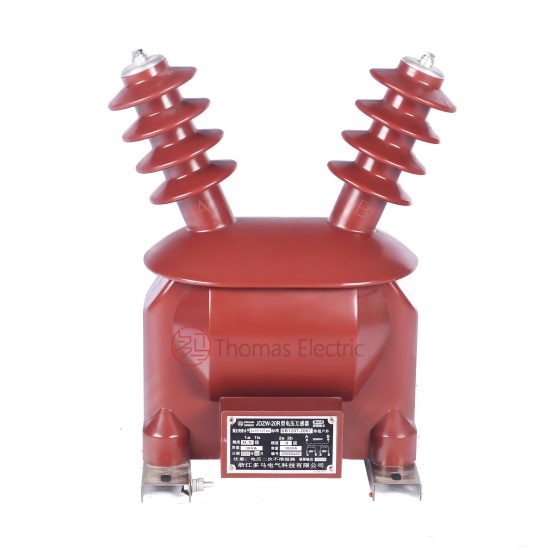
The JDZW-20 is a single-phase, indoor/outdoor rated, cast-resin insulated voltage transformer (VT) designed for operation in 21kV (IEC nominal) or 20kV (domestic system) medium-voltage networks. Its primary function is to accurately step down high system voltages to standardized secondary levels—typically 100 V or 100/√3 V—for use in metering, protection relaying, and monitoring systems. Unlike legacy oil-immersed designs, the JDZW-20 employs vacuum pressure impregnated (VPI) epoxy resin encapsulation, which provides superior dielectric strength, environmental resilience, and fire safety.
Operating Principle of Cast-Resin Insulation
Cast-resin insulation in the JDZW-20 utilizes a two-component cycloaliphatic epoxy resin system cured under vacuum and pressure to eliminate voids and moisture entrapment. This process ensures homogeneous dielectric properties throughout the insulation matrix. The primary and secondary windings are fully embedded within this solid resin block, which acts as both mechanical support and electrical insulation. The absence of liquid dielectrics eliminates risks of leakage, flammability, and maintenance-intensive oil sampling. The resin’s thermal class is typically F (155°C), allowing continuous operation at ambient temperatures up to 40°C with a 10K temperature rise margin under rated load. Dielectric tests confirm a power frequency withstand voltage of 46 kV rms for 1 minute between primary and ground, and 3 kV rms between secondary terminals and ground, per IEC 61869-3 requirements.
Advantages Over Oil-Immersed Designs
Compared to traditional oil-filled VTs, the JDZW-20 offers significant operational and safety benefits. Its dry-type construction eliminates fire hazards, making it suitable for indoor substations, urban switchgear rooms, and confined industrial facilities where fire codes restrict flammable materials. The solid resin structure is impervious to humidity, dust, and chemical contaminants, ensuring stable performance in coastal, tropical, or polluted environments (up to pollution severity Class III per IEC 60815). Mechanical robustness is enhanced by the monolithic resin body, which resists vibration and seismic loads (tested to 0.5g horizontal acceleration). Additionally, the absence of oil simplifies disposal at end-of-life and reduces lifecycle costs by eliminating oil testing, filtration, and replacement procedures. Weight is also reduced by approximately 30% compared to equivalent oil units, easing handling and mounting.
Typical Applications Overview
The JDZW-20 is engineered for critical roles in modern distribution infrastructure. It is commonly deployed in 20kV radial or ring-main networks serving commercial complexes, manufacturing plants, and municipal utilities. In renewable energy applications, it provides accurate voltage feedback for solar inverters and wind turbine grid synchronization systems operating at 21kV. Its high accuracy class (0.2 or 0.5 for metering) ensures compliance with billing regulations, while its protection-class outputs (3P or 6P) reliably drive overvoltage, undervoltage, and directional relays. The unit’s compact footprint allows integration into SF6-insulated switchgear or air-insulated cubicles without requiring external bushings or oil containment pits.
Technical Specifications
The JDZW-20 adheres strictly to international and domestic standards, delivering precise performance under defined service conditions. Below is a comprehensive specification table followed by environmental and operational parameters.
| Parameter | Value |
|---|---|
| System Voltage (IEC) | 21 kV |
| System Voltage (Domestic) | 20 kV |
| Primary Voltage | 21/√3 kV (for grounded systems) |
| Secondary Voltage(s) | 100/√3 V (metering), 100 V (protection) |
| Voltage Ratio | 21000/√3 : 100/√3 : 100 |
| Accuracy Class (Metering) | 0.2 or 0.5 (per IEC 61869-3) |
| Accuracy Class (Protection) | 3P or 6P |
| Rated Output (per winding) | 30 VA (0.2 class), 50 VA (0.5 class), 100 VA (3P/6P) |
| Insulation Level (Um/Ur) | 24/21 kV |
| Power Frequency Withstand Voltage | 46 kV rms, 1 min (primary to ground) |
| Lightning Impulse Withstand Voltage | 125 kV peak (1.2/50 μs wave) |
| Core Material | Grain-Oriented Electrical Steel (GOES), M4 grade |
| Insulation System | VPI Epoxy Resin, Thermal Class F (155°C) |
| Polarity | Reduced Polarity (standard) |
Standard Service Conditions
The JDZW-20 is rated for standard service conditions as defined in IEC 61869-3: ambient temperature range of -25°C to +40°C, relative humidity up to 95% non-condensing, and installation altitude not exceeding 1000 meters above sea level. For altitudes between 1000 m and 3000 m, derating factors apply: for every 100 m above 1000 m, the rated voltage must be reduced by 1.25%, or the insulation level increased accordingly. The unit is designed for continuous operation at 1.2 times rated voltage for up to 8 hours per day without degradation in accuracy or insulation integrity. Harmonic distortion tolerance is specified up to 5% THD at fundamental frequency (50/60 Hz), with phase error maintained within ±10 minutes for 0.2-class windings under such conditions.
Electrical Performance Tolerances
Voltage error and phase displacement are tightly controlled. For a 0.2-class secondary winding at 25–100% of rated burden and unity power factor, voltage error must not exceed ±0.2%, and phase error must remain within ±10 minutes. At 0.5-class, tolerances widen to ±0.5% and ±20 minutes, respectively. Protection windings (3P/6P) allow ±3% or ±6% voltage error at 100% burden and 0.8 lagging power factor. Burden is defined as the total apparent power (in VA) drawn by connected devices; exceeding rated burden degrades accuracy and may cause overheating. The JDZW-20 includes thermal overload capability: it can sustain 150% of rated output for 30 seconds without permanent damage, supporting transient fault conditions during relay coordination studies.
Typical Applications
The JDZW-20 serves diverse roles across modern power systems, leveraging its accuracy, reliability, and compact design.
Substation Secondary Metering
In 20kV/21kV distribution substations, the JDZW-20 provides the reference voltage for revenue-grade energy meters. Its 0.2-class secondary winding ensures billing accuracy compliant with national regulatory frameworks (e.g., China’s DL/T 448). The transformer is typically connected phase-to-ground in effectively grounded systems, delivering 100/√3 V to three-phase kWh meters. Because cast-resin insulation exhibits minimal aging under continuous voltage stress, long-term drift is less than 0.05% per year, reducing recalibration frequency. Integration with smart metering infrastructure (AMI) is seamless due to low harmonic distortion and stable phase response, critical for time-of-use and reactive energy billing.
Industrial Power Distribution
Within large industrial facilities—such as cement plants, steel mills, or data centers—the JDZW-20 monitors bus voltage for motor protection relays and power quality analyzers. Its immunity to electromagnetic interference (EMI) from variable-frequency drives (VFDs) stems from the shielded resin encapsulation and twisted-pair secondary leads. In arc-flash mitigation schemes, the VT supplies undervoltage signals to fast-trip relays that isolate faults within 3–5 cycles. The unit’s robust mechanical design withstands vibrations from nearby transformers or switchgear operations, maintaining calibration integrity over decades of service.
Renewable Energy Integration
Solar photovoltaic (PV) farms and onshore wind installations frequently operate at 21kV collector voltages. The JDZW-20 enables grid-code compliance by providing precise voltage magnitude and phase angle to inverters and SCADA systems. During low-voltage ride-through (LVRT) events, its ability to maintain output accuracy down to 15% of nominal voltage (for short durations) supports inverter stability. The dry-type construction is ideal for remote or unmanned sites, eliminating oil maintenance in harsh desert or alpine environments. Multiple units are often paralleled on ring-main feeders to provide redundancy for critical renewable generation assets.
Rural and Suburban Distribution Networks
In rural electrification projects, the JDZW-20 is mounted on pole-top platforms or pad-mounted switchgear to serve agricultural pumps, village microgrids, and telecom towers. Its lightweight design (typically 65–75 kg) simplifies aerial installation using standard utility cranes. The unit’s hydrophobic resin surface resists tracking in high-humidity or salt-laden atmospheres, common in coastal regions. For single-phase applications, it enables cost-effective voltage monitoring without requiring full three-phase VT banks, reducing capital expenditure for utilities expanding last-mile connectivity.
Compliance with International Standards
The JDZW-20 is engineered to meet stringent global and regional standards, ensuring interoperability and safety.
IEC 61869-3 Compliance Details
IEC 61869-3 governs the performance, testing, and marking of inductive voltage transformers. The JDZW-20 complies fully with Clause 5 (rated values), Clause 6 (accuracy requirements), and Clause 7 (tests). Key verifications include: temperature rise test (max 60K for windings), short-circuit withstand (not applicable for VTs, but open-circuit stability confirmed), and partial discharge measurement (<10 pC at 1.2 Um/√3). Markings include rated voltage factor (1.2 for continuous, 1.5 for 30 s), accuracy classes, and vector group (single-phase, so no group designation). Type tests were performed at an ISO/IEC 17025-accredited laboratory, with results documented in the manufacturer’s test report.
GB/T 20840.3 Alignment
China’s national standard GB/T 20840.3 mirrors IEC 61869-3 but includes localized requirements. Notably, GB/T mandates additional seismic testing (horizontal acceleration of 0.3g for Zone B installations) and stricter pollution performance for Class IV environments. The JDZW-20 meets these via reinforced core clamping and extended creepage distance (≥30 mm/kV for 21kV, yielding ≥630 mm). Domestic certification includes CQC (China Quality Certification) and type approval from State Grid Corporation of China (SGCC), confirming compatibility with Chinese protection relays like those from NARI or XJ Group.
Key Differences Between IEC and Domestic Standards
While IEC 61869-3 focuses on functional performance, GB/T 20840.3 emphasizes environmental durability and grid-specific interoperability. For example, GB/T requires verification of accuracy under 1.9Un for 8 hours (simulating ferroresonance conditions), whereas IEC only mandates 1.5Un for 30 seconds. Additionally, GB/T specifies mandatory secondary terminal labeling in Chinese characters alongside IEC symbols. Despite these differences, the JDZW-20’s dual compliance allows export to ASEAN markets while meeting domestic procurement rules.
On-Site Testing Procedures
Post-installation verification ensures the JDZW-20 performs within specifications before energization.
Insulation Resistance Test
Using a 2500 V DC megohmmeter, measure insulation resistance between primary winding and ground, and between secondary windings and ground. Acceptance criteria: ≥1000 MΩ at 20°C. Correct for temperature using the formula RT2 = RT1 × 2(T1−T2)/10. Values below 500 MΩ indicate moisture ingress or resin cracking and require drying or replacement. Perform before and after high-voltage tests to detect insulation degradation.
Turns Ratio Test
Apply a low AC voltage (50–100 V) to the primary and measure secondary output with a calibrated voltmeter. Calculate actual ratio and compare to nameplate (e.g., 21000/√3 : 100/√3 = 210:1). Tolerance: ±0.2% for 0.2-class, ±0.5% for 0.5-class. Use a dedicated turns ratio tester (e.g., Omicron CT Analyzer) for automated comparison. Deviations beyond tolerance suggest winding shorts or incorrect tap selection.
Polarity Test
Verify reduced polarity using the DC kick method: briefly connect a 6–12 V battery across primary terminals (H1+, H2−) and observe secondary voltage deflection with a center-zero galvanometer. A momentary positive kick at X1 confirms correct polarity. Incorrect polarity causes 180° phase reversal, leading to metering errors or relay misoperation. This test is mandatory for differential or directional protection schemes.
Power Frequency Withstand Voltage Test
Apply 46 kV rms at 50 Hz between primary and grounded tank for 1 minute. Monitor for flashover, excessive leakage current (>1 mA), or audible discharge. Use a calibrated test transformer with overcurrent trip set at 5 mA. This test validates insulation integrity after transport and installation stresses. Do not perform if insulation resistance is below 1000 MΩ.
Open-Circuit Characteristic Test
Gradually increase primary voltage from 0 to 1.5 × Un (31.5 kV) while measuring secondary voltage and excitation current. Plot Vsec vs Iexc. The knee point should occur above 1.2 Un. Excessive excitation current (>5% of rated secondary current at 1.0 Un) indicates core saturation or inter-turn faults. This test is critical for detecting ferroresonance susceptibility in ungrounded systems.
Preventive Maintenance Guide
Although cast-resin VTs require minimal maintenance, periodic checks extend service life and prevent failures.
Periodic Inspection Schedule
Conduct visual and electrical inspections annually. Check for surface cracks, tracking marks, or discoloration on the resin housing. Clean with dry cloth or mild detergent if contaminated. Verify terminal tightness (torque: 15 N·m for M8 bolts). Measure insulation resistance and compare to baseline. After severe weather (lightning, flooding), perform immediate post-event inspection. Every 5 years, repeat full on-site tests (ratio, polarity, withstand) to validate long-term performance.
Maintenance Intervals and Fault Diagnosis
| Interval | Action | Fault Indicator |
|---|---|---|
| Annual | Visual inspection, IR scan, insulation resistance | Hot spots >10K above ambient, IR <500 MΩ |
| 5 Years | Full electrical tests, secondary burden verification | Ratio error >0.5%, phase error >30 min |
| After Fault | Withstand test, open-circuit curve | Flashover, distorted excitation curve |
Common failure modes include secondary winding open-circuit (causing dangerous overvoltages) and resin delamination due to thermal cycling. If secondary voltage reads zero under load, check fuses first—VT secondaries must always be fused per IEC 61869-3 Clause 10. Never operate with open secondary.
Conclusion
The JDZW-20 21kV cast-resin voltage transformer represents a benchmark in medium-voltage instrumentation, combining precision engineering with robust construction. Its VPI epoxy resin insulation delivers exceptional dielectric performance and environmental resilience, eliminating the fire and maintenance liabilities of oil-filled alternatives. Compliance with both IEC 61869-3 and GB/T 20840.3 ensures global applicability while meeting stringent domestic grid requirements. With accuracy classes down to 0.2 for metering and 3P for protection, it supports critical functions from revenue billing to fault detection across industrial, utility, and renewable sectors. Rigorous on-site testing protocols and a straightforward preventive maintenance regime further enhance reliability. Designed for a service life of 25–30 years under standard conditions, the JDZW-20 offers a low total cost of ownership and long-term operational stability. Its compact form factor and dual indoor/outdoor rating make it adaptable to evolving grid architectures, from smart substations to distributed energy resources. For engineers specifying instrumentation in 20kV/21kV networks, the JDZW-20 provides a technically sound, standards-compliant solution that prioritizes safety, accuracy, and longevity.
Q1: Can the JDZW-20 be used in ungrounded 21kV systems?
Yes, but with caution. In ungrounded or resonant-grounded systems, the voltage factor must be verified for 1.9Un continuous operation per GB/T 20840.3. The standard JDZW-20 is rated for 1.2Un continuous and 1.5Un for 30 seconds; special-order units with enhanced core design are required for sustained overvoltage conditions.
Q2: What is the maximum allowable secondary burden?
Burden must not exceed the rated output for the selected accuracy class: 30 VA for 0.2-class, 50 VA for 0.5-class, and 100 VA for 3P/6P protection windings. Exceeding burden increases voltage error and phase displacement beyond tolerance limits.
Q3: Is the JDZW-20 suitable for indoor GIS installations?
Yes. Its compact dimensions (typically 380×220×520 mm) and lack of flammable materials make it compatible with gas-insulated switchgear (GIS) and metal-enclosed indoor substations. Ensure adequate clearance to grounded parts per IEC 62271-200.
Q4: How does temperature affect accuracy?
Accuracy is guaranteed between -5°C and +40°C ambient. Outside this range, error may increase by up to 0.1% per 10°C deviation. For extreme climates, select units with extended temperature compensation windings.
Q5: Can multiple secondary windings be loaded simultaneously?
Yes, provided the total burden on each winding does not exceed its individual rating. The magnetic circuit is designed to handle independent loading on metering and protection secondaries without cross-interference.