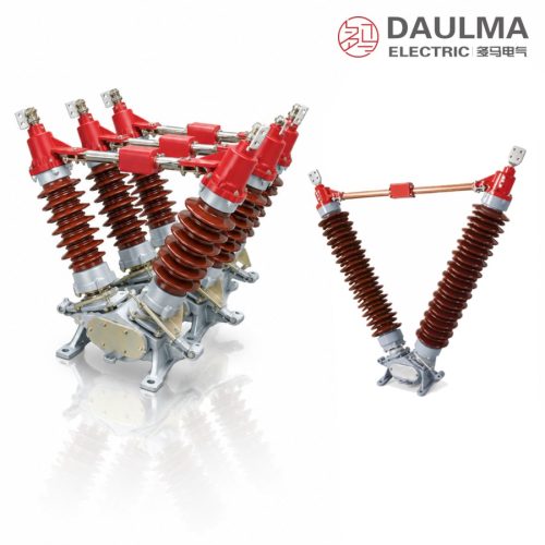
Product Overview
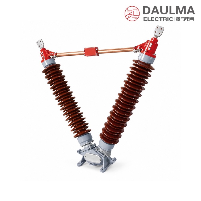
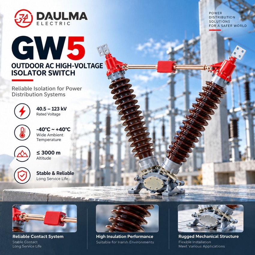
The GW5 is a double-post V-type horizontal-rotation outdoor disconnector for three-phase 50 Hz networks, isolating lines and equipment with a clearly visible break of about 90°. It cannot break load or short-circuit current and is used together with a circuit breaker. Each pole carries two support-post insulators at a 50° included angle on a common base, driven by a manual or motorised mechanism through a three-phase linkage; pollution-proof insulators suit heavily polluted sites. The catalogue outline table covers 40.5, 72.5 and 126 kV, and electrical ratings follow the technical agreement.
Product Display
Model Designation
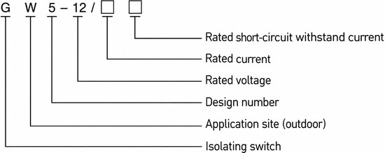
Model format: G W 5 -12 / □ □
- G — disconnector
- W — place of use: outdoor
- 5 — design sequence number
- 12 — rated voltage, kV (designation example; the catalogue outline table covers 40.5 / 72.5 / 126 kV)
- □ — rated current, A
- □ — rated short-circuit withstand current, kA
Service Conditions
- Altitude: 1000 to 3000 m
- Ambient temperature: not above +40 ℃ and not below −30 ℃ (−40 ℃ for cold areas)
- Wind pressure: not exceeding force 8
- Seismic intensity: not above intensity 8
- No frequent violent vibration at the installation site
- General type: site free from gases, vapours, chemical deposits, salt mist, dust or other explosive or corrosive substances that seriously affect insulation and conductivity
- Pollution-proof type: suitable for heavily polluted areas, free from substances that may cause fire or explosion
Construction
Each pole is built from a base, two support-post insulators, outgoing terminals and contacts that form the main conducting circuit. The two insulators stand perpendicular to the base on bearings at its ends, set at a 50° included angle, and carry the conducting part above them, which rotates through about 90° with the posts to open or close the circuit with a wide, clearly visible break; contact pressure is maintained by self-cleaning finger contacts.
The poles are coupled by a three-phase linkage and driven by a manual or motorised operating mechanism, with open / close position indication on the motorised version. Extended-creepage pollution-proof insulators are offered for severely polluted coastal and industrial regions to prevent pollution flashover, and because the disconnector cannot break load or short-circuit current it is always used together with a circuit breaker.
Technical Data
| Item | Value | Remark |
|---|---|---|
| Network | Three-phase AC, 50 Hz | — |
| Rated voltage | 40.5 / 72.5 / 126 kV | Range covered by the catalogue outline dimension table; the designation example shows GW5-12 |
| Rated current | Fixed by technical agreement | Follows the equipment nameplate |
| Rated short-time withstand current | Fixed by technical agreement | Follows the equipment nameplate |
| Rated peak withstand current | Fixed by technical agreement | Follows the equipment nameplate |
| Power-frequency / lightning impulse withstand voltage | Fixed by technical agreement | Follows the equipment nameplate |
| Post included angle / rotation | 50° / about 90° | Double-post V-type, clearly visible break |
| Operating mechanism | Manual or motorised | Three-phase linkage; position indication on motorised version |
Standards
The source catalogue pages for the GW5 name no specific product standard. The series is rated for three-phase AC 50 Hz networks, and rated current, rated short-time withstand current, rated peak withstand current and the power-frequency / lightning-impulse withstand voltages are all fixed by the order technical agreement and follow the equipment nameplate; the outline dimension table covers 40.5, 72.5 and 126 kV.
Installation & Dimensions
Installation Diagram
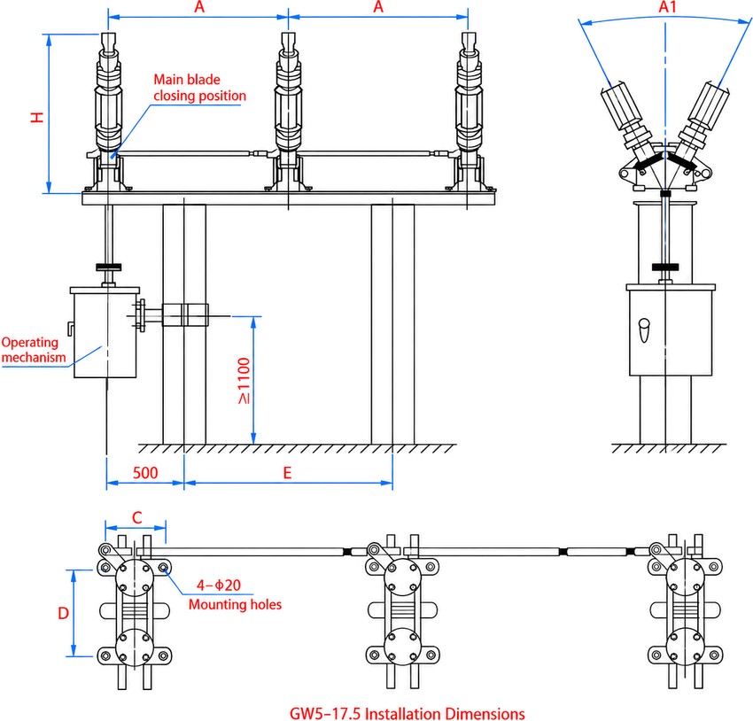
Assemble the V-type poles on the common frame at the specified phase spacing (A), fix each base through the four Φ20 mounting holes on the C / D span, and couple the poles to the operating mechanism with the three-phase linkage shaft. All dimensions are in mm: A = phase spacing, A1 = V opening width, H = height, E = mechanism-centre distance, C / D = base mounting-hole span. Keep at least 1100 mm clear below the mechanism for the operator platform, allow the 500 mm terminal offset, verify free ~90° travel, correct contact seating and the full visible break before energising, and bond the bases to the earth grid.
| No. | Rated voltage (kV) | A | A1 | H | E | C | D |
|---|---|---|---|---|---|---|---|
| 1 | 40.5 | 1200 | 1075 | 1070 | 1400 | 240 | 300 |
| 2 | 72.5 | 1600 | 1285 | 1295 | 2200 | 240 | 300 |
| 3 | 126 | 2000 | 1660 | 1695 | 3000 | 240 | 300 |