Article Content
11kV Cast-Resin Current Transformer LFS-10 for Metering and Protection – IEC 61869-2 Standard
Introduction to the LFS-10 Current Transformer
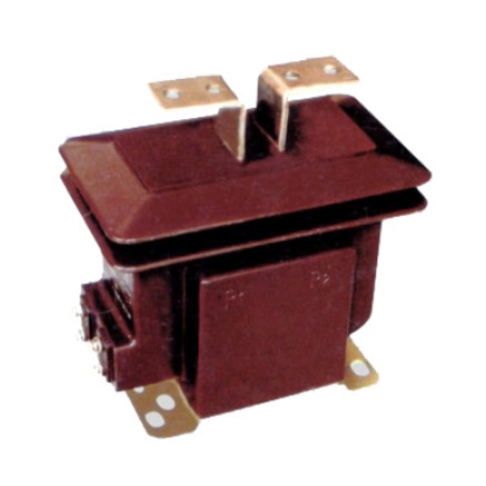
The LFS-10 is a dry-type, cast-resin insulated current transformer (CT) engineered for reliable operation in 11kV (IEC) / 10kV (domestic) indoor medium-voltage switchgear systems. Designed in strict compliance with IEC 61869-2 and GB/T 20840.2, this instrument transformer delivers high accuracy for both metering and protection applications across utility substations, industrial facilities, and renewable energy interconnection points. Its solid epoxy resin encapsulation eliminates fire hazards and environmental risks associated with oil-filled alternatives, making it ideal for confined or public-access installations.
Operating Principle of Cast-Resin Insulation
Cast-resin insulation in the LFS-10 utilizes vacuum pressure impregnation (VPI) epoxy technology to fully encapsulate the primary conductor and secondary windings within a homogeneous, void-free dielectric matrix. This process ensures uniform electric field distribution, suppresses partial discharges below 10 pC at rated voltage, and provides excellent resistance to thermal cycling and mechanical stress. The resin compound—typically a cycloaliphatic epoxy system—offers superior tracking resistance (CTI > 600 V), UV stability, and hydrophobic surface properties that prevent moisture ingress even under high humidity conditions (up to 95% RH). Unlike oil-immersed CTs, the LFS-10 requires no maintenance of insulating fluid, eliminating risks of leakage, degradation, or flammability in indoor environments.
Advantages Over Oil-Immersed Designs
The LFS-10’s cast-resin construction provides critical operational advantages over traditional oil-filled CTs. First, it is inherently non-flammable, meeting IEC 60695-11-10 flame class V-0 requirements—essential for installations in buildings, tunnels, or urban substations where fire safety codes prohibit combustible materials. Second, its compact footprint (typical dimensions: 180 mm height × 120 mm width × 85 mm depth) enables integration into space-constrained switchgear panels such as RMU or metal-clad designs. Third, the absence of oil eliminates outgassing, oxidation, and dielectric aging mechanisms, resulting in a service life exceeding 30 years under normal operating conditions. Additionally, the LFS-10 exhibits lower thermal time constants, allowing faster response to transient overcurrents without core saturation during fault conditions.
Typical Applications Overview
The LFS-10 is predominantly deployed in indoor 11kV distribution networks requiring dual-function CTs for revenue metering (Class 0.5 or 0.2S) and protective relaying (Class 5P10 or 5P20). Common use cases include ring main units (RMUs) in urban grids, motor control centers in heavy industry, solar farm collector substations, and hospital or data center backup power systems. Its robust design supports continuous operation at ambient temperatures from –25°C to +40°C and altitudes up to 1,000 meters above sea level without derating. The transformer’s low remanence (<10% of saturation flux density) ensures minimal residual magnetism after fault clearance, preserving accuracy during subsequent measurement cycles—a critical feature for automated reclosing schemes in smart grids.
Technical Specifications
The LFS-10 current transformer is engineered to meet stringent electrical and environmental performance criteria defined by international and domestic standards. Below is a representative specification table for standard configurations; custom ratios and accuracy classes are available upon request.
| Parameter | Value |
|---|---|
| Rated Voltage (Ur) | 11 kV (IEC) / 10 kV (GB) |
| System Frequency | 50 Hz or 60 Hz |
| Primary Current (Ip) | 50 A to 3150 A (standard steps) |
| Secondary Current (Is) | 1 A or 5 A |
| Accuracy Classes | Metering: 0.2S, 0.5S, 1 Protection: 5P10, 5P20, 10P10 |
| Rated Output (Burden) | 2.5 VA to 30 VA (per class) |
| Insulation Level (LI/AC) | 75 kV / 28 kV (1.2/50 μs & 1 min) |
| Short-Time Thermal Current | 25 kA for 1 s (at Ip = 630 A base) |
| Dynamic Withstand Current | 62.5 kA peak |
| Core Material | Grain-Oriented Electrical Steel (GOES), M6 grade |
| Insulation System | VPI Epoxy Resin, Class F (155°C) |
| Ambient Temperature Range | –25°C to +40°C |
| Relative Humidity | Up to 95% non-condensing |
| Altitude Limit | ≤1,000 m (derating required above) |
Standard Service Conditions
The LFS-10 is rated for indoor installation under normal service conditions as defined in IEC 61869-2 Clause 4. Environmental parameters must not exceed: ambient temperature range of –25°C to +40°C, daily average relative humidity ≤95%, and maximum altitude of 1,000 meters. At altitudes between 1,000 m and 2,000 m, the power frequency withstand voltage must be reduced by 1% per 100 m above 1,000 m. The transformer is not suitable for outdoor exposure unless housed in an IP4X-rated enclosure. Condensation must be prevented through proper ventilation or heating elements in high-humidity environments to avoid surface tracking on the resin housing.
Electrical Performance Parameters
Key electrical characteristics include a composite error tolerance of ≤±0.2% for Class 0.2S at 100% rated current and ≥25% burden, ensuring compliance with revenue metering regulations. For protection class 5P20, the transformer maintains a ratio error within ±1% and phase displacement ≤±60 minutes at 20× rated current with rated burden. The knee-point voltage (Vk) typically exceeds 200 V for 5P20 cores, guaranteeing adequate saturation margin during high-magnitude faults. Secondary winding resistance (Rct) is tightly controlled (e.g., 0.15 Ω ±5% for 5 A secondary) to minimize burden-induced errors in long cable runs.
Typical Applications
The LFS-10 cast-resin current transformer serves diverse roles in modern power systems, leveraging its dual-accuracy capability and compact form factor.
Substation Secondary Metering
In 11kV/0.4kV distribution substations, the LFS-10 provides Class 0.5S or 0.2S accuracy for billing-grade energy measurement. Installed on outgoing feeders or incomers, it interfaces with digital multifunction meters (e.g., IEC 61850-9-2 LE sampled values or analog 4–20 mA outputs). The low phase error (<10 minutes at 100% In) ensures precise power factor calculation, critical for reactive energy billing. Its resin housing resists contamination from dust or chemical vapors common in urban substations, maintaining long-term calibration stability without recalibration for 10+ years.
Industrial Power Distribution
Within manufacturing plants, the LFS-10 monitors large motors (≥500 kW), transformers, and capacitor banks. Dual-core variants supply one winding to revenue meters (0.5S) and another to motor protection relays (5P10). The high short-circuit withstand (25 kA/1s) protects against mechanical damage during bus faults, while the fast thermal response prevents overheating during prolonged overloads. In arc flash mitigation systems, accurate current replication enables selective tripping within 30 ms, minimizing downtime.
Renewable Energy Integration
Solar and wind farms utilize the LFS-10 at the 11kV collector substation interface. During cloud transients or grid disturbances, the CT must accurately replicate rapidly changing currents without saturation. The GOES core’s low hysteresis loss and controlled permeability ensure linearity down to 1% of rated current—essential for anti-islanding detection and low-voltage ride-through (LVRT) compliance. Its immunity to DC offset (from inverter harmonics) prevents false tripping of protection relays.
Rural and Suburban Distribution Networks
In remote areas with limited maintenance access, the LFS-10’s maintenance-free design reduces lifecycle costs. Deployed in pole-mounted or pad-mounted switchgear, it supports AMI (Advanced Metering Infrastructure) via communication-enabled meters. The wide operating temperature range accommodates desert or alpine climates, while the resin’s UV resistance (when shielded) prevents embrittlement. Its consistent ratio accuracy across decades ensures fair billing even with infrequent meter audits.
Compliance with International Standards
The LFS-10 is certified to IEC 61869-2:2012 (“Instrument transformers – Part 2: Additional requirements for current transformers”) and aligns with China’s GB/T 20840.2-2014 standard, ensuring global interoperability.
IEC 61869-2 Compliance Details
Under IEC 61869-2, the LFS-10 undergoes rigorous type tests including temperature rise (≤60 K for windings), short-circuit withstand (25 kA/1s), and impulse voltage (75 kV peak). Accuracy verification follows Clause 6.4, requiring composite error measurement at 5%, 20%, 100%, and 120% of rated current. The standard mandates partial discharge levels <10 pC at 1.2×Ur/√3, which the LFS-10 achieves through optimized resin casting and core annealing. Marking includes Ur, accuracy class, rated output, and polarity indicators per IEC requirements.
GB/T 20840.2 Alignment
While GB/T 20840.2 closely mirrors IEC 61869-2, key differences exist: Chinese standards specify 10 kV as nominal system voltage (vs. 11 kV IEC), require slightly higher power frequency test voltage (32 kV vs. 28 kV), and mandate additional seismic testing (0.3g horizontal acceleration) for earthquake-prone regions. The LFS-10 meets both by design—its insulation system exceeds 32 kV AC withstand, and mechanical resonance testing confirms stability up to 15 Hz natural frequency.
Testing and Certification Requirements
Certification involves routine tests (100% production): turns ratio, polarity, insulation resistance (>1,000 MΩ at 2,500 V DC), and power frequency withstand. Type tests (per batch) include temperature rise, short-circuit, and accuracy validation in accredited labs (e.g., KEMA, CESI, or CEPREI). Each unit receives a test report traceable to national metrology institutes, with calibration certificates available for metrological applications.
On-Site Testing Procedures
Post-installation verification ensures the LFS-10 performs within specifications before energization.
Insulation Resistance Test
Apply 2,500 V DC between primary-to-secondary/ground and secondary-to-ground using a megohmmeter. Acceptance criterion: ≥1,000 MΩ at 20°C. Correct for temperature using RT2 = RT1 × 2(T1–T2)/10. Low readings indicate moisture ingress or resin cracking—requiring drying or replacement.
Turns Ratio Test
Inject 1–5 A AC at 50 Hz into the primary and measure secondary current. Calculate actual ratio = Ip/Is. Tolerance: ±0.2% for metering classes, ±1% for protection. Use a precision current comparator (e.g., 0.05% accuracy) for Class 0.2S validation.
Polarity Test
Verify reducing polarity using the DC kick method: apply momentary 6–12 V DC to primary (P1→P2); observe secondary voltage spike direction with an oscilloscope. Positive deflection at S1 confirms correct polarity. Incorrect polarity causes 180° phase reversal—critical for differential protection schemes.
Power Frequency Withstand Voltage Test
Apply 28 kV RMS (IEC) or 32 kV RMS (GB) at 50 Hz for 1 minute between primary and grounded secondary/housing. No flashover or breakdown permitted. Ramp voltage at ≤1 kV/s to avoid transient overstress. Perform only if factory test records are unavailable.
Short-Circuit Test (for CT)
Not applicable as a field test due to high fault currents. Instead, validate thermal rating via nameplate comparison and ensure busbar torque matches manufacturer specs (typically 15–20 N·m for M10 studs). Check for mechanical deformation post-fault using visual inspection and ratio retest.
Preventive Maintenance Guide
Although maintenance-free, periodic checks extend service life and detect latent issues.
Periodic Inspection Schedule
Conduct annual visual inspections: check for cracks, discoloration, or tracking marks on resin; verify terminal tightness (re-torque to 18 N·m if loose); clean dust with dry air (<0.5 MPa). Every 5 years, perform insulation resistance and ratio tests. After any system fault >10 kA, immediately retest ratio and polarity.
Fault Diagnosis and Troubleshooting
Common issues include: (1) Ratio drift—caused by core demagnetization; remedy with AC degaussing at 120% In. (2) High insulation resistance drop—indicates moisture; bake at 80°C for 24 hours in dry oven. (3) Excessive heating—check for open-circuited secondary (never operate CT secondary open!). Always de-energize before handling.
Maintenance Intervals Summary
| Interval | Action |
|---|---|
| Annually | Visual inspection, terminal torque check, cleaning |
| Every 5 Years | Insulation resistance, turns ratio, polarity test |
| Post-Fault | Full electrical retest if fault >10 kA |
| Every 10 Years | Optional calibration against reference standard |
Conclusion
The LFS-10 11kV cast-resin current transformer represents a benchmark in reliability, accuracy, and safety for indoor medium-voltage applications. Its VPI epoxy resin insulation eliminates fire hazards and environmental liabilities inherent in oil-filled designs, while the GOES silicon steel core ensures metrological precision across metering (0.2S/0.5S) and protection (5P10/5P20) functions. Full compliance with IEC 61869-2 and GB/T 20840.2 guarantees interoperability in global markets, supported by rigorous type testing and traceable calibration. With a design life of 25–30 years under standard service conditions, the LFS-10 minimizes total cost of ownership through zero fluid maintenance, resistance to thermal cycling, and immunity to partial discharge degradation. Its compact form factor facilitates integration into modern switchgear, and its robust short-circuit withstand capability ensures survivability during grid faults. For engineers specifying instrumentation in 11kV networks—from urban substations to renewable plants—the LFS-10 delivers uncompromised performance, regulatory compliance, and long-term operational integrity without compromise.
Frequently Asked Questions (FAQ)
Q1: Can the LFS-10 be used in 10kV domestic systems?
Yes. While rated at 11kV per IEC standards, the LFS-10 is fully compatible with 10kV systems (common in China and other regions). Its insulation level (75/28 kV) exceeds the requirements for 10kV (typically 70/30 kV per GB), ensuring safe operation.
Q2: Is it safe to leave the secondary winding open-circuited?
No. An open-circuited CT secondary can generate hazardous voltages (>2 kV) during primary current flow, risking insulation failure and personnel injury. Always short-circuit secondary terminals before disconnecting meters or relays.
Q3: What burden should I specify for a 5P20 protection class?
The rated burden (e.g., 15 VA) must match the connected relay’s input impedance plus wiring losses. For 5P20, the CT must maintain accuracy at 20× rated current with this exact burden. Undersizing burden causes premature saturation; oversizing wastes capacity.
Q4: How does altitude affect LFS-10 performance?
Above 1,000 m, reduce power frequency withstand voltage by 1% per 100 m. For example, at 1,500 m, test voltage = 28 kV × (1 – 0.05) = 26.6 kV. No derating needed for current ratings below 2,000 m.
Q5: Can I install multiple LFS-10 units on the same busbar?
Yes, but maintain minimum spacing of 25 mm between housings to prevent magnetic coupling errors. Ensure busbar centerlines align with CT windows to avoid ratio distortion from off-axis fields.
Q6: Does the LFS-10 support digital output (e.g., IEC 61850)?
The base LFS-10 provides analog output (1 A/5 A). For digital integration, pair it with a merging unit (MU) that samples the analog signal and outputs IEC 61850-9-2 LE packets.