Article Content
JDZW-35R 11kV Cast-Resin Current Transformer for Substation Metering and Protection – IEC 61869-2 Certified
Introduction to the JDZW-35R Current Transformer
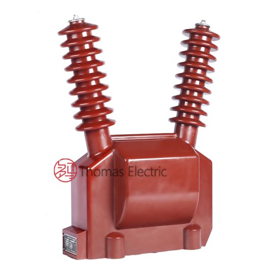
The JDZW-35R is a medium-voltage, outdoor-rated, cast-resin insulated current transformer (CT) designed for accurate current measurement and reliable protective relay operation in 11kV distribution networks (corresponding to a domestic system voltage of 10kV). Engineered in strict compliance with IEC 61869-2 and GB/T 20840.2, this device leverages vacuum pressure impregnation (VPI) epoxy resin technology to deliver superior dielectric strength, environmental resilience, and long-term stability without the fire or leakage hazards associated with oil-filled alternatives.
Operating Principle of Cast-Resin Insulation
Cast-resin insulation in the JDZW-35R employs a high-purity cycloaliphatic epoxy resin system processed under vacuum and pressure to eliminate voids and moisture entrapment. The primary conductor—typically a solid copper or aluminum busbar—is centrally positioned within a toroidal core made of grain-oriented electrical steel (GOES), which is then fully encapsulated in the cured resin matrix. This monolithic structure provides uniform electric field distribution, high tracking resistance (>600 V according to IEC 60587), and excellent thermal conductivity (0.2–0.3 W/m·K). The absence of liquid insulation eliminates maintenance requirements related to oil sampling, degassing, or tank integrity checks. Additionally, the resin’s coefficient of thermal expansion closely matches that of copper and steel, minimizing mechanical stress during thermal cycling from –40°C to +40°C ambient conditions.
Advantages Over Oil-Immersed Designs
Compared to traditional oil-immersed CTs, the JDZW-35R offers significant operational and safety benefits. Its dry-type construction eliminates fire risk (classified as non-flammable per IEC 60695), making it suitable for urban substations, indoor switchgear, and environmentally sensitive areas. The compact footprint—approximately 30% smaller than equivalent oil units—reduces space requirements in pad-mounted or pole-top installations. Furthermore, the cast-resin body exhibits superior resistance to UV radiation, salt fog (tested per IEC 60068-2-52), and pollution (creepage distance ≥25 mm/kV for 11kV systems). Unlike oil-filled units, which may suffer from moisture ingress leading to reduced breakdown strength, the JDZW-35R maintains stable dielectric performance over its 25–30 year design life, even in high-humidity coastal or industrial environments.
Typical Deployment Scenarios
The JDZW-35R is commonly deployed in utility-owned 11kV/10kV distribution substations for revenue metering (accuracy class 0.2S or 0.5S) and feeder protection (class 5P10 or 10P10). It is also specified in industrial plants with medium-voltage motor control centers, renewable energy interconnection points (e.g., solar farms feeding into 11kV grids), and rural electrification projects where maintenance access is limited. Its robust IP54-rated terminal box protects secondary connections from dust and water ingress, while the integral mounting flange enables direct bolting to bus supports or transformer bushings.
Technical Specifications
The JDZW-35R adheres to precise electrical and mechanical parameters defined by international and domestic standards. Below is a comprehensive specification table followed by environmental and operational constraints.
| Parameter | Value |
|---|---|
| Rated System Voltage (IEC) | 11 kV |
| Rated System Voltage (Domestic) | 10 kV |
| Maximum System Voltage | 12 kV |
| Primary Current Rating | 50 A to 3000 A (standard); custom up to 4000 A |
| Secondary Current | 1 A or 5 A (user-selectable at time of order) |
| Accuracy Classes | Metering: 0.2S, 0.5S; Protection: 5P10, 10P10, 10P20 |
| Rated Burden (VA) | 2.5, 5, 10, 15, 30 VA (per accuracy class) |
| Insulation Level (LI/AC) | 95 kV lightning impulse / 42 kV power frequency (1 min) |
| Short-Time Thermal Current | 25 kA for 1 s (Ith) |
| Dynamic Withstand Current | 62.5 kA peak (Idyn) |
| Core Material | Grain-Oriented Electrical Steel (GOES), M4 grade |
| Insulation Material | Vacuum Pressure Impregnated (VPI) cycloaliphatic epoxy resin |
| Ambient Temperature Range | –40°C to +40°C |
| Altitude Limit | ≤1000 m above sea level (derating required above 1000 m) |
| Relative Humidity | Up to 95% non-condensing |
| Creepage Distance | ≥275 mm (25 mm/kV × 11 kV) |
| Weight | Approx. 28 kg (varies with ratio) |
Standard Service Conditions
The JDZW-35R is rated for continuous operation under standard service conditions as defined in IEC 61869-2 Clause 4. These include an ambient temperature range of –40°C to +40°C, relative humidity up to 95% (non-condensing), and installation altitude not exceeding 1000 meters. At altitudes between 1000 m and 2000 m, the power frequency withstand voltage must be derated by 1% per 100 m above 1000 m. For example, at 1500 m, the AC test voltage becomes 42 kV × (1 – 0.05) = 39.9 kV. The transformer is designed for three-phase systems with balanced loading; however, it can tolerate unbalanced conditions provided the primary current does not exceed the rated value continuously. The terminal box is sealed to IP54, protecting against dust ingress and water splashes from any direction, critical for outdoor pole-mounted applications.
Electrical Performance Tolerances
Per IEC 61869-2, the JDZW-35R meets strict error limits under defined burdens. For a 0.2S class unit at 100% rated current and rated burden, the current error must not exceed ±0.2%, and phase displacement must be ≤±10 minutes. At 1% of rated current, the error tolerance widens to ±0.75%. Protection-class CTs (e.g., 5P10) must limit composite error to ≤5% when subjected to 10 times rated current at rated burden. The turns ratio tolerance is ±0.25% for metering classes and ±1.0% for protection classes. These tolerances are verified during factory testing using calibrated reference standards traceable to national metrology institutes.
Typical Applications
The JDZW-35R serves diverse roles across modern power infrastructure, combining metrological precision with rugged reliability.
Substation Secondary Metering
In utility-owned 11kV distribution substations, the JDZW-35R is integrated into revenue metering circuits to measure energy consumption for billing purposes. Installed on outgoing feeders, it typically operates in 0.2S or 0.5S accuracy class with a 5 A secondary output connected to a digital kWh meter via shielded twisted-pair cable. The low phase error ensures accurate reactive energy measurement, critical for power factor correction billing. The cast-resin housing withstands transient overvoltages from switching operations or lightning surges, preventing insulation failure that could compromise metering integrity. In smart grid deployments, these CTs interface with AMI (Advanced Metering Infrastructure) systems, requiring long-term ratio stability—achieved through the low hysteresis loss of the GOES core.
Industrial Power Distribution
Large manufacturing facilities often operate their own 11kV/10kV internal distribution networks. Here, the JDZW-35R provides both metering for internal cost allocation and protection for motors, transformers, and busbars. For example, a 1250 kVA induction motor fed at 11kV draws approximately 65 A full-load current; a JDZW-35R with 100/5 A ratio and 5P10 class supplies input to a multifunction protective relay (e.g., overcurrent, earth fault). The CT’s high saturation point (Vk ≥ 150 V for 5P10) ensures linear response during fault conditions, enabling precise time-current coordination. The outdoor rating allows installation adjacent to switchyards without climate-controlled enclosures.
Renewable Energy Integration
Solar photovoltaic (PV) farms frequently connect to the grid via 11kV collection systems. The JDZW-35R monitors export/import power at the point of interconnection (POI). Due to the intermittent nature of solar generation, the CT must maintain accuracy across a wide current range—from near-zero at night to peak output during midday. The 0.2S class fulfills this requirement down to 1% of rated current. Additionally, during grid faults, the CT must supply undistorted current waveforms to anti-islanding and voltage ride-through relays. The low remanence of the GOES core minimizes residual flux after fault clearance, ensuring rapid recovery for subsequent events.
Rural and Suburban Distribution Networks
In remote or semi-urban areas, the JDZW-35R is mounted on utility poles to serve clusters of residential or agricultural consumers. Its maintenance-free design is ideal where technician visits are infrequent. A typical configuration uses a 200/5 A ratio with 0.5S accuracy feeding a local data concentrator that aggregates readings from multiple feeders. The high creepage distance prevents flashovers during fog or light rain, common in humid regions. The transformer’s mechanical robustness also resists vandalism and wildlife contact—key concerns in exposed locations.
Compliance with International Standards
The JDZW-35R is engineered to satisfy both global and Chinese regulatory frameworks, ensuring interoperability and safety.
IEC 61869-2 Compliance Details
IEC 61869-2:2012 specifies general requirements for instrument transformers, with Part 2 dedicated to current transformers. The JDZW-35R complies with all mandatory clauses, including insulation coordination (Clause 6), temperature rise limits (≤60 K for resin, measured by resistance method), short-circuit withstand capability, and accuracy verification under defined burdens. Dielectric tests include 1-minute power frequency withstand at 42 kV and lightning impulse at 95 kV (1.2/50 µs waveform). The standard also mandates marking requirements: model number, ratio, accuracy class, burden, polarity dot, and manufacturer identification must be permanently molded into the resin housing—features incorporated into the JDZW-35R design.
Alignment with GB/T 20840.2
GB/T 20840.2-2014 is the Chinese national adoption of IEC 61869-2, with minor editorial differences but identical technical content. The JDZW-35R is dual-certified, bearing both CE and CQC marks. One notable alignment is the use of 10kV as the nominal system voltage in domestic documentation, while IEC documentation references 11kV. However, the insulation levels (42/95 kV) and thermal ratings remain consistent. Chinese utilities often require additional type tests per DL/T 725, such as partial discharge measurement (<10 pC at 1.2 × Um/√3), which the JDZW-35R routinely passes due to its void-free resin casting.
Testing and Certification Requirements
Full type testing per IEC 61869-2 includes temperature rise, short-circuit, accuracy, and dielectric tests. Routine tests performed on every unit include: visual inspection, winding continuity, polarity check, turns ratio verification (±0.25% for metering), and power frequency withstand (42 kV for 1 min). The JDZW-35R is certified by third-party laboratories accredited to ISO/IEC 17025, with test reports available upon request. Certificates confirm compliance with RoHS 3 (EU 2015/863) for restricted substances, ensuring environmental safety during end-of-life disposal.
On-Site Testing Procedures
Post-installation verification ensures the JDZW-35R performs as specified under actual site conditions.
Insulation Resistance Test
Using a 2500 V DC megohmmeter, measure insulation resistance between primary winding and ground, and between secondary windings and ground. Acceptance criterion: ≥1000 MΩ at 20°C. Correct for temperature using RT2 = RT1 × 2(T1–T2)/10. Low values indicate moisture ingress or surface contamination; clean terminals with isopropyl alcohol and retest. This test validates the integrity of the cast-resin barrier after transportation and handling.
Turns Ratio Test
Apply a low-voltage AC source (e.g., 10 V at 50 Hz) to the primary and measure secondary voltage. Calculate ratio as Vp/Vs. Compare to nameplate; tolerance is ±0.25% for metering CTs, ±1.0% for protection. Use a dedicated ratio tester (e.g., Omicron CT Analyzer) for higher accuracy. Deviations beyond tolerance suggest winding damage or incorrect tap selection.
Polarity Test
Verify reducing polarity using the DC kick method: briefly apply a 6–12 V battery across primary terminals (H1 to H2). Observe secondary voltage on a DC voltmeter connected to X1 and X2. A momentary positive deflection confirms correct polarity (H1 and X1 are同名端). Incorrect polarity causes 180° phase shift, leading to metering errors or relay misoperation.
Power Frequency Withstand Voltage Test
Apply 42 kV RMS at 50 Hz between primary and ground for 1 minute. Secondary windings must be short-circuited and grounded. Monitor for flashover or excessive leakage current (<1 mA). This test is typically performed only during commissioning if factory test records are unavailable. Use a calibrated HV test set with overcurrent trip.
Excitation (Saturation) Characteristic Test
For protection CTs, perform excitation test per IEEE C57.13. Apply variable AC voltage to secondary winding (primary open) and record current. Plot Vsec vs Iexc; knee-point voltage (Vk) must meet design spec (e.g., ≥150 V for 5P10). Low Vk indicates core saturation risk during faults, compromising protection coordination.
Preventive Maintenance Guide
Although cast-resin CTs are largely maintenance-free, periodic checks extend service life and prevent unexpected failures.
Annual Visual and Functional Inspection
Inspect for physical damage (cracks, discoloration), terminal corrosion, and loose connections. Clean housing with mild detergent; avoid solvents that degrade resin. Verify secondary circuit continuity and grounding integrity. Check for abnormal heating using infrared thermography during peak load—hotspots >10°C above ambient warrant investigation. Ensure terminal box gasket remains pliable and seals properly.
Five-Year Comprehensive Maintenance
Every five years, repeat insulation resistance and turns ratio tests. Perform excitation test on protection-class units to detect core degradation. Review historical load profiles; if primary current consistently exceeds 120% of rating, consider replacement to avoid thermal aging. Document all findings in asset management systems for lifecycle analysis.
Maintenance Intervals and Fault Diagnosis
| Interval | Action | Fault Indicator |
|---|---|---|
| Annually | Visual inspection, IR scan, terminal torque check | Cracking, overheating, loose lugs |
| 5 Years | Insulation resistance, ratio, excitation test | Ratio drift >1%, Vk drop >15% |
| After Fault | Full electrical test suite | Relay misoperation, metering discrepancy |
Common faults include secondary open-circuit (causing dangerous overvoltage), core saturation from DC offset, and moisture ingress through damaged terminal seals. Immediate replacement is recommended if insulation resistance falls below 100 MΩ or ratio error exceeds twice the tolerance limit.
Conclusion
The JDZW-35R 11kV cast-resin current transformer represents a technically mature solution for modern medium-voltage networks, balancing metrological precision, protective reliability, and environmental resilience. Its VPI epoxy resin insulation eliminates fire hazards and maintenance burdens inherent in oil-filled designs, while the GOES core ensures low losses and stable accuracy across wide current ranges—from 1% to 120% of rated current for metering applications, and up to 20× rated current for protection duties. Full compliance with IEC 61869-2 and GB/T 20840.2 guarantees interoperability in global and domestic markets, supported by rigorous factory and field testing protocols. With a design life of 25–30 years under standard service conditions, the JDZW-35R delivers exceptional lifecycle value for utilities, industrial operators, and renewable energy developers. Its robust construction withstands harsh outdoor environments, from arid deserts to humid coastal zones, making it a dependable choice for critical metering and protection functions in 11kV (10kV) distribution infrastructure. When installed and maintained per manufacturer guidelines, this CT provides decades of trouble-free service with minimal intervention, aligning with industry trends toward asset longevity and operational efficiency.