JN15-24/31.5 Indoor High-Voltage Earthing Switch - featured

JN15-24/31.5 Indoor High-Voltage Earthing Switch, Motorised or Manual

JN15-24/31.5 Indoor High-Voltage Earthing Switch, 24 kV

  • 24 kV indoor earthing switch, 50 / 60 Hz systems
  • 31.5 kA short-time withstand current for 4 s
  • 80 kA rated peak withstand and making current
  • Resin-insulated, silver-plated copper live parts
  • Manual spring or motorised mechanism, interlocked
  • Mechanical life rated at 2000 operating cycles

Product Overview

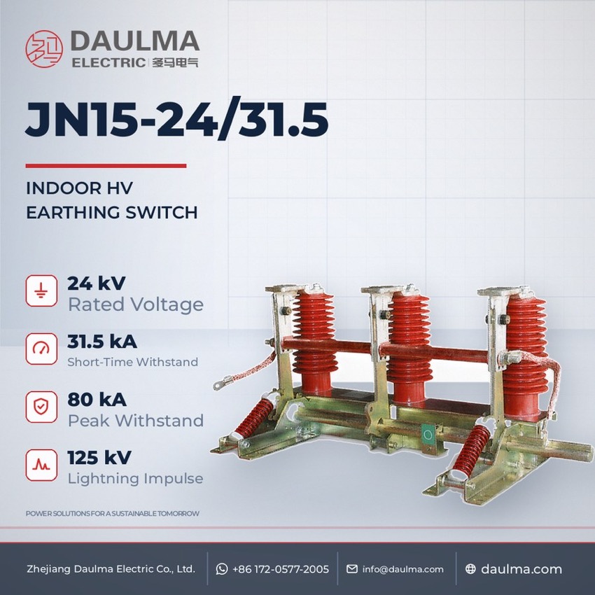
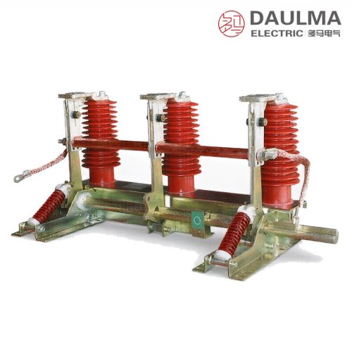
The JN15-24/31.5 is an indoor high-voltage earthing switch for 24 kV, 50/60 Hz three-phase systems, designed to GB 1985-2004 and IEC 62271-102. Fitted inside metal-enclosed switchgear, it bonds a de-energised circuit to earth for safe maintenance and is interlocked with the associated circuit breaker or disconnector so it closes only onto a dead circuit. Resin-insulated poles carry silver-plated electrolytic copper live parts, oversized contacts hold high contact pressure, and the quick-action spring mechanism makes up to 80 kA peak short-circuit current and carries 31.5 kA for 4 s.

Product Display
JN15-24/31.5 Indoor High-Voltage Earthing Switch - display

JN15-24/31.5 Indoor High-Voltage Earthing Switch - poster_display

Model Designation

JN15-24/31.5 Indoor High-Voltage Earthing Switch - model

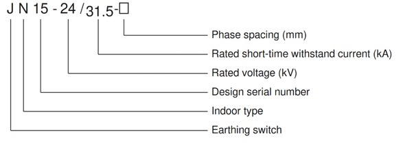
Model format: J N 15 – 24 / 31.5 – □

  • J – earthing switch
  • N – place of use: indoor
  • 15 – design number
  • 24 – rated voltage, kV
  • 31.5 – rated short-time withstand current, kA
  • □ – phase spacing (between-pole distance), mm

Service Conditions

  • Altitude: not exceeding 1000 m
  • Ambient air temperature: upper limit +40 °C, lower limit -10 °C
  • Seismic intensity: not exceeding 8 degrees
  • Installation site free from flammable or explosive substances, severe dust, chemical corrosion and violent vibration

Construction

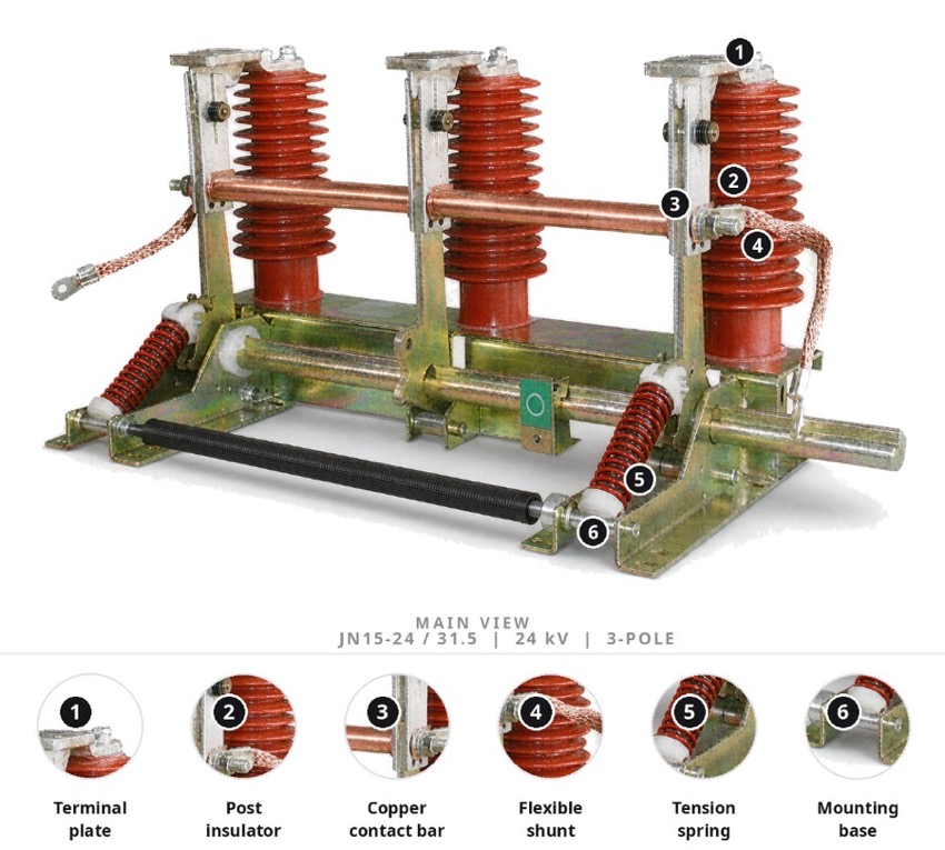
Each pole is carried on a resin-insulated support insulator, and the live parts are made of silver-plated electrolytic copper of 99.9% purity. The earth blade is connected directly to the drive shaft, so all three poles make or break the earth connection simultaneously; the blade and fixed contacts are dimensioned generously to hold a high contact pressure, keep the ohmic contact resistance low and minimise metal wear over the service life, even under the thermal and mechanical stresses of a short circuit.

A quick-action spring mechanism makes the opening and closing speed independent of the operator, and the switch can be supplied with a manual spring-operated or a motorised mechanism. It is interlocked with the associated circuit breaker so the earth connection can be made only when the main circuit is de-energised, and a retaining pin blocks closing while maintenance work is in progress.

Technical Data

No. Item Unit Data
1 Rated voltage kV 24
2 Rated frequency Hz 50 / 60
3 Rated short-time withstand current kA 31.5
4 Rated short-circuit duration s 4
5 Rated peak withstand current kA 80
6 Rated short-circuit making current kA 80
7 Rated power-frequency withstand voltage (1 min) kV 65 (relative to earth and between phases)
8 Rated lightning impulse withstand voltage kV 125
9 Mechanical life operations 2000
Selection note: Confirm the 24 kV, 50/60 Hz network ratings first, then verify the 31.5 kA short-time withstand against the prospective three-phase short-circuit current and the 80 kA peak withstand against the maximum impulse current, with the 4 s duration matched to the back-up protection operating time. Choose the phase spacing to suit the busbar arrangement of the cubicle, select a manual spring or motorised mechanism (DC control supply preferred for motorised versions), and specify any live-line indication, interlock type and the left-hand or right-hand lever position when ordering.

Standards

The JN15-24/31.5 complies with GB 1985-2004 for AC high-voltage disconnectors and earthing switches and with IEC 62271-102. It is supplied as an integral assembled earthing switch suitable for various types of indoor medium- and high-voltage metal-enclosed switchgear used in 24 kV systems.

Technical note: Rated values are taken from the catalogue parameter table; where a value is fixed by the order, the technical agreement and the nameplate of the delivered switch govern, and the certified dimensional drawing for the ordered phase spacing must be confirmed before cubicle preparation.

Installation & Dimensions

Installation Diagram
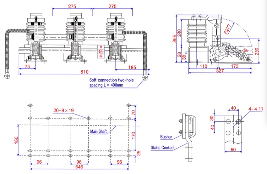
JN15-24/31.5 Indoor High-Voltage Earthing Switch - installation

Installation, commissioning and maintenance must be carried out by qualified personnel, and the switch may be handled only on de-energised circuits; insert the retaining pin so it cannot be closed while work is in progress. Inspect the switch one to two times per year and immediately after a severe short-circuit event: clean the conductive parts and insulator surfaces, wash the pivots with alcohol or a suitable solvent and re-grease them with industrial petroleum jelly, check that all fastening bolts are tight and the earthing connection is sound, and replace any damaged or permanently deformed blades, contacts or pressure springs. Never operate the switch when there is no earthed fixed contact, never exceed its rated voltage, and run several opening and closing tests before returning it to service.

Safety notice: The earthing switch may be closed only onto a circuit that has been isolated and proved de-energised; it is interlocked with the associated disconnector and circuit breaker so that it cannot be closed onto a live circuit nor opened while the circuit is earthed. It carries short-time fault current and can make short-circuit current, but it breaks no load. Keep the interlocks and the retaining pin in service and never bypass them.

FAQs

A disconnector isolates an unloaded circuit and provides a visible insulation gap, while an earthing switch bonds the already de-energised circuit to earth to protect personnel and equipment during maintenance. In many cubicles the two functions are combined and mechanically interlocked so the earthing switch can close only after isolation.

The rated short-time withstand current must equal or exceed the prospective three-phase short-circuit current at the installation point for the declared 4 s duration. This thermal-stability check is the key criterion when selecting the earthing switch for a given switchgear position.

Yes. Its rated short-circuit making current is 80 kA peak, so it can close onto a faulted circuit and earth it safely, limiting damage to other equipment inside the switchgear. The contacts and blade are dimensioned to survive the thermal and mechanical stresses involved.

Both arrangements are available. The standard version uses a manual spring-charged mechanism whose quick action makes the operating speed independent of the operator, and on request a motorised mechanism is supplied for remote or interlocked control, preferably with a DC control supply.

The earthing switch is rated for 2000 mechanical operating cycles. Because the quick-action spring mechanism fixes the opening and closing speed, wear stays low across the service life when the pivots are kept clean and greased.

Yes. On request the switch can be equipped with a sensor and a voltage-presence indicator, and it can be fitted with a mechanical or electromagnetic interlock that prevents energising a circuit that is still earthed. Specify the lever position and indication requirement when ordering.

Inquiry for JN15-24/31.5 Indoor High-Voltage Earthing Switch, Motorised or Manual:

Send your project requirements. Our team will reply with technical details and quotation.

Fast response Technical support OEM / ODM