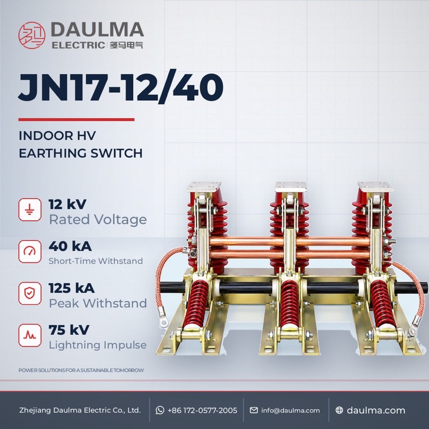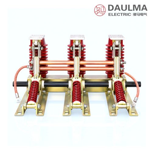
JN17-12/40 Combined Indoor High-Voltage Earthing Switch - featured

JN17-12/40 Combined Indoor High-Voltage Earthing Switch for 3-10 kV

JN17-12/40 Combined Indoor High-Voltage Earthing Switch, 12 kV

  • Combined indoor earthing switch for 3-10 kV systems
  • Rated short-time withstand current of 40 kA
  • Short-circuit making capacity protects cubicle gear
  • Five phase-centre distances, 210 mm up to 275 mm
  • Optional live-voltage indicating device supplied
  • G suffix marks the high-altitude type, 50/60 Hz

Product Overview

The JN17-12/40 is a combined indoor high-voltage earthing switch for 3-10 kV, 50/60 Hz systems, rated 12 kV, that bonds de-energised switchgear circuits to earth for maintenance. Three earth knives on support insulators over a common frame couple through one shaft, interlocked with the disconnector, breaker or cubicle door. It carries a 40 kA short-time withstand current, and its short-circuit making capacity protects other cubicle equipment; the combined type can include a live-voltage indicating device. Five frames cover phase-centre distances of 210-275 mm; G marks the high-altitude type.

Product Display
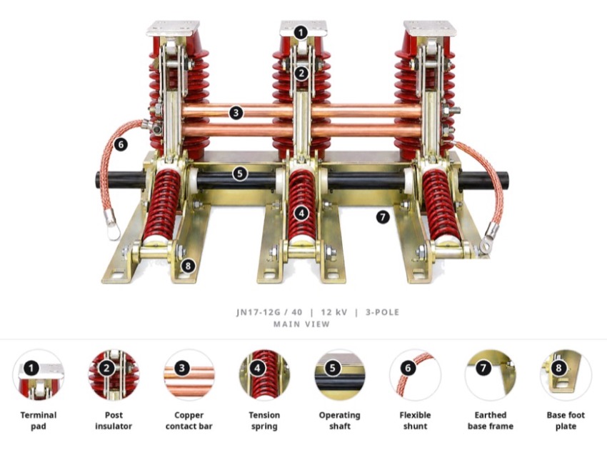
JN17-12/40 Combined Indoor High-Voltage Earthing Switch - display

JN17-12/40 Combined Indoor High-Voltage Earthing Switch - poster_display

Model Designation

JN17-12/40 Combined Indoor High-Voltage Earthing Switch - model

Model format: J N 17 – 12 (G) / 40 – □

  • J – earthing switch
  • N – place of use: indoor
  • 17 – design number (also built as the JN15-12G/40 variant)
  • 12 – rated voltage, kV
  • (G) – high-altitude type, optional suffix
  • 40 – rated short-time withstand current, kA
  • □ – phase-centre (between-pole) distance, mm: 210 / 220 / 230 / 250 / 275
  • Example: JN17-12G/40-230 is the high-altitude type at 40 kA with 230 mm pole spacing

Service Conditions

  • Altitude: not above 1000 m
  • Ambient air temperature: upper limit +40 °C, lower limit -10 °C
  • Seismic intensity: not above 8 degrees
  • Site free from flammable or explosive hazard, severe dust, chemical corrosion and violent vibration

Construction

The switch uses a combined three-pole arrangement in which the earth knives are mounted on support insulators above a common frame and coupled through a transmission shaft to the operating mechanism, so all three poles make or break the earth connection together. The knives engage static contacts sized to close reliably onto a short-circuit current, and the mechanism can be interlocked with the associated switchgear or with the cubicle door to prevent mal-operation.

As a combined type the assembly can be furnished with a live-voltage indicating device that shows the energised state of the busbar. A flexible earth conductor, standard length 240 mm unless otherwise agreed, links the switch to the earthing network, and the frame itself is bonded to that network to complete the protective path; five phase-centre distances allow the frame to match cubicles of different makers.

Technical Data

Item Unit Data
Rated voltage kV 12 (applicable to 3-10 kV systems)
Rated frequency Hz 50 / 60
Rated short-time withstand current kA 40
Phase-centre (between-pole) distance mm 210 / 220 / 230 / 250 / 275
High-altitude type — G suffix
Selection note: Take the phase-centre distance from the busbar layout of the cubicle; the five frames cover 210, 220, 230, 250 and 275 mm with overall dimension H of 655 to 810 mm. Order the G high-altitude type for sites above 1000 m, state whether a live-voltage indicating device is required and of which type, and state whether the 240 mm flexible earth connection must be lengthened. The mechanism interlock must suit the associated disconnector or circuit breaker of the switchgear.

Standards

The source datasheet names no specific product standard for the JN17-12/40; the ratings follow the order technical agreement and the nameplate of the delivered switch. Only the rated voltage, the 50/60 Hz frequency, the 40 kA rated short-time withstand current and the five phase-centre distances are published, while short-circuit duration, rated peak withstand current, rated short-circuit making current and the rated insulation level are fixed by agreement.

Technical note: Catalogue values and the outline drawing are for cubicle preparation only; confirm the certified dimensional drawing for the ordered phase-centre distance before installation. Where a value is fixed by the order, the technical agreement and the nameplate of the delivered switch govern over the catalogue page.

Installation & Dimensions

Installation Diagram
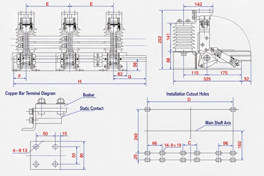
JN17-12/40 Combined Indoor High-Voltage Earthing Switch - installation

Fix the earthing-switch frame to the cubicle mounting plane at the selected phase-centre distance, keeping the earth knives and static contacts clear of obstructions. Couple the three poles to the operating mechanism through the transmission shaft and connect the flexible earth conductor, standard length 240 mm unless otherwise agreed. Before energising, verify simultaneous and full contact seating of all three poles, correct interlock action with the associated switchgear or cubicle door, and reliable bonding of the frame to the earth network.

Model E (mm) F (mm) G (mm) H (mm) D (mm)
JN17-12/40-210 210 50 185 655 516
JN17-12/40-220 220 50 185 675 536
JN17-12/40-230 230 50 185 695 556
JN17-12/40-250 250 50 185 735 596
JN17-12/40-275 275 50 210 810 646
Safety notice: An earthing switch may only be closed onto a circuit that has been isolated and proved de-energised. The JN17-12/40 is interlocked with the associated disconnector or circuit breaker so that it cannot be closed onto a live circuit, and the circuit cannot be re-energised while the earth knives are closed. It carries and can make short-time current but breaks no load; keep the interlocks in service and let qualified personnel operate and maintain the switch with the frame bonded to the earth network.

FAQs

J stands for an earthing switch and N for indoor use, 17 is the design number and 12 the rated voltage in kV. The optional G marks the high-altitude type, 40 is the rated short-time withstand current in kA, and the trailing figure after the second dash gives the phase-centre distance between poles in mm.

It matches various types of indoor high-voltage switchgear on 3-10 kV, 50/60 Hz systems and provides the protective earth for de-energised equipment during inspection and maintenance. Its short-circuit making capacity also helps protect the other apparatus inside the cubicle if the switch closes onto a fault.

The earthing switch is supplied as a combined assembly that can be furnished together with a live-voltage indicating device showing the energised state of the busbar. The indicator is optional, and its type must be stated when ordering.

The source datasheet publishes the 12 kV rated voltage, the 50/60 Hz frequency and the 40 kA rated short-time withstand current. Short-circuit duration, peak withstand current, short-circuit making current and insulation level are not tabulated and follow the nameplate and the technical agreement.

Five frames are offered with pole centre distances of 210, 220, 230, 250 and 275 mm. The overall dimension H grows from 655 mm on the smallest frame through 675, 695 and 735 mm to 810 mm on the 275 mm frame.

State the model, the phase-centre distance, whether a live-voltage indicating device is required and its type, and whether the flexible earth connection must be longer than the standard 240 mm. Service conditions are altitude up to 1000 m, ambient air from -10 °C to +40 °C, seismic intensity not above 8, and a site free from flammable or explosive hazard, severe dust, chemical corrosion and violent vibration.

Inquiry for JN17-12/40 Combined Indoor High-Voltage Earthing Switch for 3-10 kV:

Send your project requirements. Our team will reply with technical details and quotation.

Fast response Technical support OEM / ODM