Product Overview
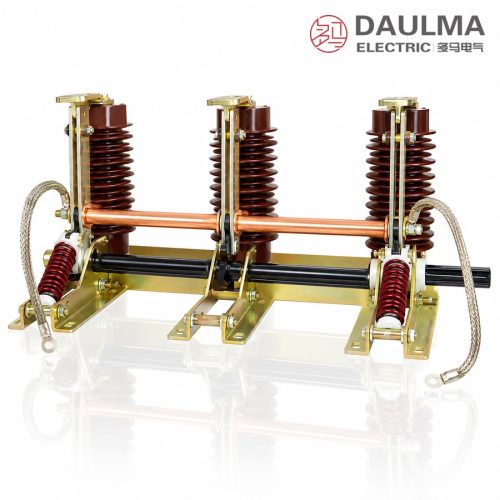
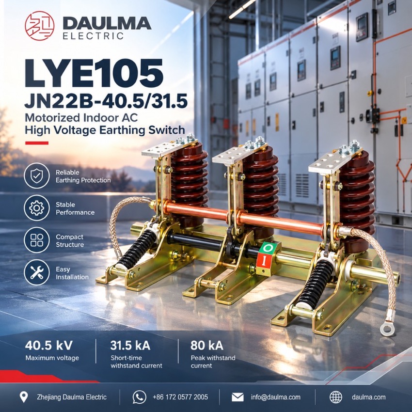
The JN22B-40.5/31.5 is an indoor high-voltage earthing switch developed from the JN15 type for 40.5 kV maximum voltage (35 kV rated), 50 Hz systems, compliant with IEC 129 and IEC 62271-102. It matches KYN□-40.5 and other metal-enclosed switchgear as the earthing-protection element: once the feeder is isolated and proved dead, its three earth knives bond the circuit to earth, interlocked with the switchgear or door against mal-operation. Silver-plated contacts make short-circuit current; the switch carries 31.5 kA for 4 s with 80 kA peak; five phase-centre distances of 280-400 mm are offered.
Product Display
Model Designation
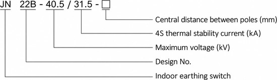
Model format: JN 22B – 40.5 / 31.5 – □
- JN – indoor earthing switch
- 22B – design number
- 40.5 – maximum (rated) voltage, kV
- 31.5 – 4 s thermal-stability (short-time withstand) current, kA
- □ – central distance between poles, mm
- Example: JN22B-40.5/31.5-360 is the 31.5 kA type with 360 mm pole centres
Service Conditions
- Ambient temperature: -10 °C to +40 °C
- Altitude: not above 1000 m
- Relative humidity: daily average not above 95%, monthly average not above 90%
- Seismic intensity: not above 8 degrees
- Site free from corrosive or flammable gas and without frequently intense vibration
Construction
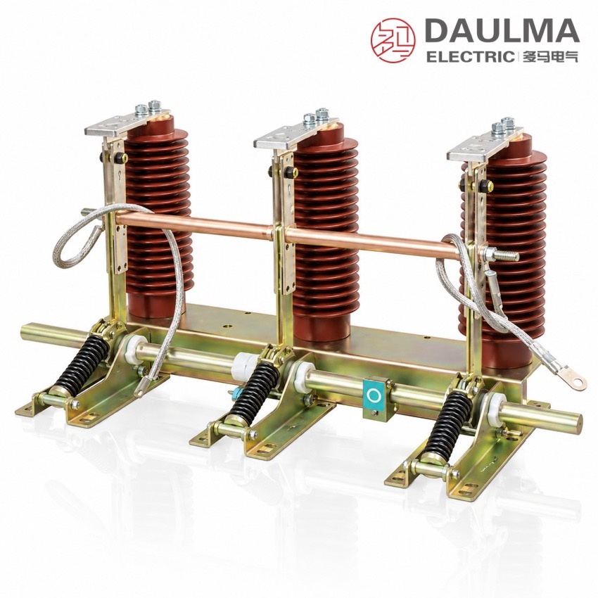
The three earth knives are carried on support insulators above a common frame and are driven through a transmission shaft by a manual operating mechanism, so all three poles make or break the earth connection together with fast opening and closing. The knives engage silver-plated static contacts sized to close reliably onto a short-circuit current, and the compact three-pole assembly mounts inside 40.5 kV metal-enclosed switchgear.
The mechanism can be interlocked with the associated switchgear or cubicle door to prevent mal-operation, ensuring the knives close only on an isolated, de-energised circuit. Where the phase-centre distance is below 360 mm an insulation board is added between the phases, and the frame is bonded to the earth network to complete the protective path; the simple structure eases installation, commissioning and adjustment.
Technical Data
| Item | Unit | Data |
|---|---|---|
| Rated voltage | kV | 35 |
| Maximum (rated) voltage | kV | 40.5 |
| Rated frequency | Hz | 50 |
| Rated short-time withstand current | kA | 31.5 |
| Rated short-circuit duration | s | 4 |
| Rated peak withstand current | kA | 80 |
| Rated short-circuit making current | kA | 80 |
| Phase-center (between-pole) distance | mm | 280 / 300 / 350 / 360 / 400 |
| 1 min power-frequency withstand voltage (phase to earth) | kV | 95 |
| Lightning impulse withstand voltage (phase to earth) | kV | 185 |
| Standard | — | IEC 129; IEC 62271-102 |
Standards
Performance of the JN22B-40.5 complies with IEC 129 and IEC 62271-102 for high-voltage earthing switches. The rated parameter table of the type datasheet lists the switch at 35 kV rated voltage with 40.5 kV maximum voltage, the 95 kV power-frequency and 185 kV impulse withstand levels being stated phase to earth.
Installation & Dimensions
Installation Diagram
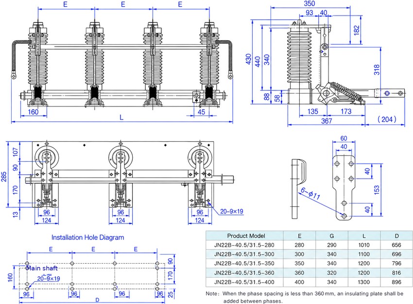
Fix the earthing-switch frame to the cubicle mounting plane through the 20 x 9 x 19 oval holes at the selected phase-centre distance, keeping the earth knives and silver-plated static contacts clear of obstructions. Couple the three poles to the manual operating mechanism through the transmission shaft, then verify simultaneous and full contact seating of all three poles, correct interlock action and bonding of the frame to the earth network before energising. Catalogue dimensions are for cubicle preparation only; confirm the certified dimensional drawing for the ordered phase-centre distance.
| Model | E (mm) | G (mm) | L (mm) | D (mm) |
|---|---|---|---|---|
| JN22B-40.5/31.5-280 | 280 | 290 | 1010 | 656 |
| JN22B-40.5/31.5-300 | 300 | 340 | 1100 | 696 |
| JN22B-40.5/31.5-350 | 350 | 340 | 1200 | 796 |
| JN22B-40.5/31.5-360 | 360 | 320 | 1200 | 816 |
| JN22B-40.5/31.5-400 | 400 | 340 | 1300 | 896 |