Product Overview
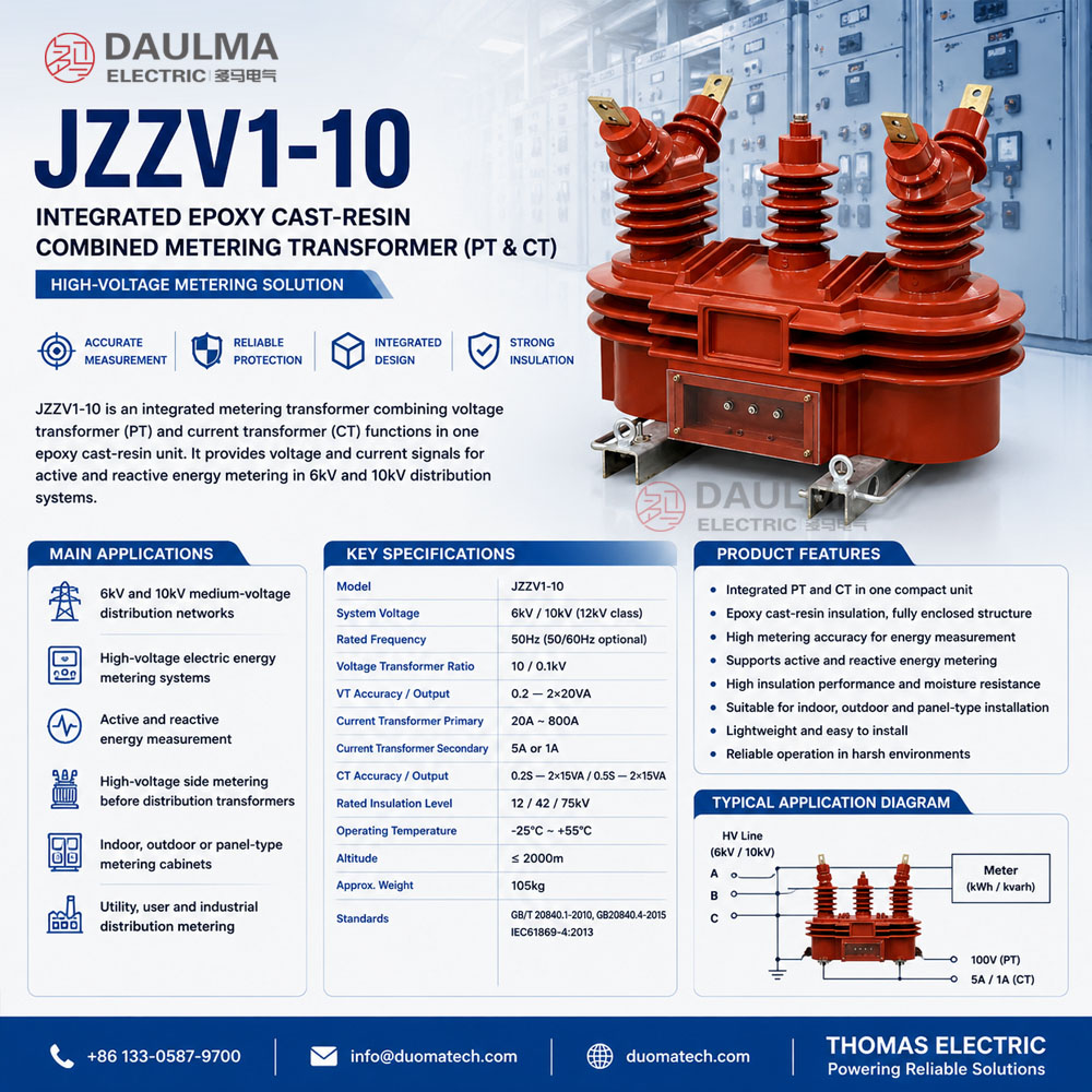
JZZV1-10 is an integrated epoxy cast-resin combined metering transformer for medium-voltage distribution systems. It combines electromagnetic voltage transformer (PT/VT) units and current transformer (CT) units in one metering assembly, providing voltage and current signals for high-voltage energy metering.
The product is suitable for 50Hz three-phase AC power systems with rated voltage of 6kV or 10kV. It is normally installed on the high-voltage side of a power transformer or inside a metering cabinet, where active energy meters and reactive energy meters directly measure the active and reactive energy of the medium-voltage line.
This product should be positioned differently from a single VT or a single CT product page. JZZV1-10 is a combined metering unit for complete high-voltage metering, using integrated PT and CT elements in one epoxy cast-resin body.
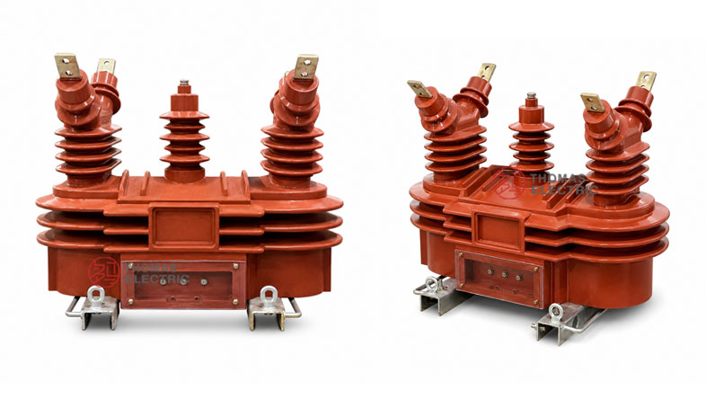
Product Display
Application Position
JZZV1-10 is used in the metering section of 6kV and 10kV power distribution systems. It is typically installed before the distribution transformer, on the high-voltage side, so that the metering instruments can measure active and reactive energy directly from the medium-voltage circuit.
Main Applications
- 6kV and 10kV medium-voltage distribution networks
- High-voltage electric energy metering systems
- Active and reactive energy measurement
- High-voltage side metering before distribution transformers
- Indoor, outdoor or panel-type metering cabinets
- Utility metering, user metering and industrial distribution metering
- Projects requiring integrated PT and CT metering signals in one unit
Key Specifications
| Item | Specification |
|---|---|
| Model | JZZV1-10 |
| Product type | Integrated combined metering transformer / PT CT combined transformer |
| Structure | Three-phase two-element combined transformer |
| Transformer components | Voltage transformer units and current transformer units |
| Insulation structure | Epoxy cast-resin insulation |
| Installation | Indoor, outdoor or panel-type metering installation according to project design |
| System voltage | 6kV and 10kV systems |
| International voltage class | 12kV class |
| Rated frequency | 50Hz ±0.5Hz; 50Hz / 60Hz can be confirmed by project specification |
| Ambient temperature | -25°C to +55°C sample condition |
| Altitude | Not more than 2000m sample condition |
| Voltage transformer ratio | 10 / 0.1kV |
| Voltage transformer accuracy / output | 0.2 — 2×20VA |
| Current transformer primary current | 20A to 800A range according to sample table |
| Current transformer secondary current | 5A or 1A according to project specification |
| Current transformer accuracy / output | 0.2S — 2×15VA; 0.5S — 2×15VA |
| Rated insulation level | 12/42/75kV |
| Approximate weight | 105kg |
| Standards | GB/T 20840.1-2010, GB20840.4-2015, IEC61869.4:2013 and project-specific requirements |
Application Fit
Suitable For
- 6kV and 10kV high-voltage energy metering projects
- 12kV class medium-voltage metering cabinets
- High-voltage side metering before distribution transformers
- Projects requiring both PT and CT signals in one integrated unit
- Active and reactive energy metering with three-phase active and reactive meters
- Metering schemes requiring CT accuracy class 0.2S or 0.5S
- Distribution networks where V/V voltage connection and two-element metering are used
Not Recommended For
- Applications requiring separate independent CT and VT installation instead of one combined unit
- Protection-only CT or protection-only VT applications where metering accuracy is not required
- High-frequency electronic transformer applications
- Systems above 12kV class without technical confirmation
- Applications requiring oil-immersed combined transformers
- Projects where the installation space cannot support the integrated body and approx. 105kg weight
Installation Conditions
- Installation position: high-voltage side of the transformer or metering cabinet section
- Rated frequency: 50Hz power-frequency AC system; 60Hz should be confirmed when required
- Ambient temperature: -25°C to +55°C sample condition
- Altitude: not more than 2000m sample condition
- Metering cabinet: reserve space for primary connection, secondary terminal wiring and inspection
- Grounding: connect the grounding terminal according to the metering cabinet grounding scheme
- Maintenance: keep resin surface clean and inspect terminals, grounding and meter wiring periodically
Technical Structure
JZZV1-10 integrates voltage transformer and current transformer functions into one epoxy cast-resin metering assembly. The voltage transformer section provides voltage signals for meters, while the current transformer section provides current signals. The combination allows high-voltage active and reactive energy to be measured without installing separate PT and CT bodies.
| Component | Description |
|---|---|
| Epoxy cast-resin body | Integrated insulation structure for outdoor, indoor or panel-type metering installation |
| Voltage transformer unit | Provides 100V secondary voltage signal for energy meters and voltage measurement |
| Current transformer unit | Provides 5A or 1A secondary current signal for active and reactive energy meters |
| Three-phase two-element structure | Combines PT and CT elements for three-phase metering schemes |
| Primary terminals | Medium-voltage line connection terminals for 6kV or 10kV circuits |
| Secondary terminal box | Terminal area for voltage and current metering outputs |
| Mounting base | Base structure for fixed installation in metering cabinets or distribution equipment |
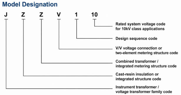
Model Designation
- J = Instrument transformer / voltage transformer family code
- Z = Cast-resin insulation or integrated structure code
- Z = Combined transformer / integrated metering structure code
- V = V/V voltage connection or two-element metering structure code
- 1 = Design sequence code
- 10 = Rated system voltage code for 10kV class applications
Technical Data
The following technical data is organized from the JZZV1-10 product sample. For international product pages, the product should be described as a 10kV combined metering transformer for 12kV class systems.
Voltage Transformer Section
| Rated Voltage Ratio | Rated Insulation Level | Accuracy Class and Rated Output | Max. Output |
|---|---|---|---|
| 10 / 0.1kV | 12/42/75kV | 0.2 — 2×20VA | 300VA |
Current Transformer Section
| Rated Primary Current | Rated Insulation Level | Accuracy Class and Rated Output | Rated Short-Time Thermal Current | Rated Dynamic Current |
|---|---|---|---|---|
| 20A | 12/42/75kV | 0.2S — 2×15VA 0.5S — 2×15VA |
5/2 kA/s | 12.5 kA |
| 30–40A | 8/2 kA/s | 20 kA | ||
| 50–60A | 10/2 kA/s | 25 kA | ||
| 75A | 16/2 kA/s | 40 kA | ||
| 100–200A | 20/2 kA/s | 50 kA | ||
| 300–500A | 25/4 kA/s | 63 kA | ||
| 600–800A | 31.5/4 kA/s | 80 kA |
Technical notes:
- One combined transformer is supplied with one selected accuracy class and rated output combination.
- The voltage transformer section provides 10/0.1kV voltage transformation for metering circuits.
- The current transformer section can be selected according to the rated primary current of the line.
- Secondary current can be 5A or 1A according to the meter and project specification.
- 0.2S accuracy is commonly used for higher-accuracy energy metering requirements.
- If required parameters exceed the listed table, they should be confirmed by agreement between manufacturer and purchaser.
Installation and Dimensions
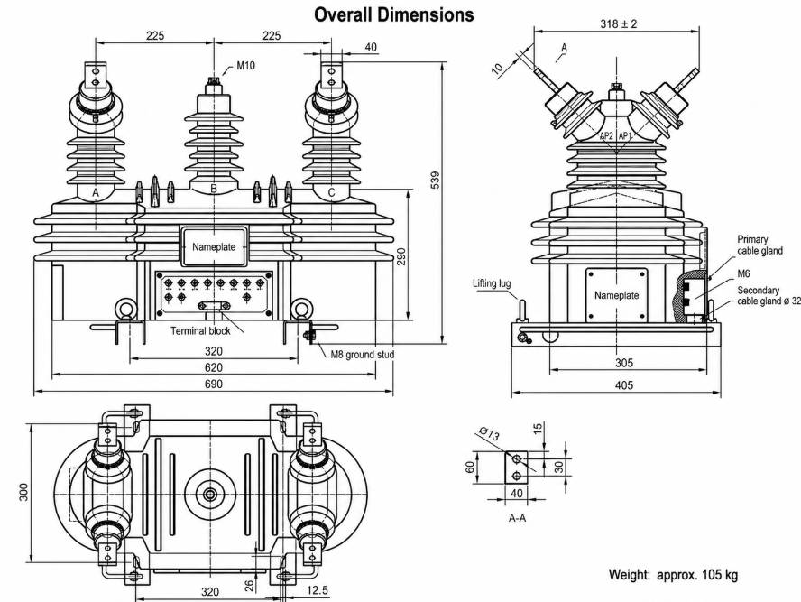
Dimension and Weight Reference
| Item | Reference Value |
|---|---|
| Overall length reference | 690mm |
| Main base length | 620mm |
| Body mounting reference | 320mm / 405mm references from drawing |
| Top phase spacing | 225mm + 225mm reference |
| Overall height | 530mm reference |
| Side width reference | 405mm |
| Plan width reference | 300mm |
| Primary terminal bolt | M10 reference |
| Secondary cable outlet | Secondary outlet box and terminal wiring area |
| Approximate weight | 105kg |
Terminal and Wiring Notes
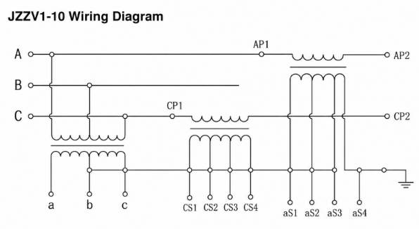
- The sample wiring diagram shows a combined PT and CT metering connection.
- Voltage transformer secondary terminals are used for voltage input to energy meters.
- Current transformer secondary terminals are used for current input to active and reactive energy meters.
- CT secondary circuits must not be open-circuited during operation.
- Metering polarity, CT ratio, PT ratio and terminal identification should be verified before commissioning.
- Grounding should follow the cabinet grounding and metering scheme.
Compliance and Testing
The product sample references GB/T 20840.1-2010, GB20840.4-2015 and IEC61869.4:2013. For export projects, the final compliance statement should be aligned with the buyer’s technical specification, local grid metering rules and approved routine test plan.
Typical Routine Tests
- Visual inspection and nameplate verification
- CT ratio and polarity test
- VT ratio and polarity test
- CT accuracy test at specified burden
- VT accuracy test at specified burden
- Power-frequency withstand voltage test
- Insulation resistance test
- Secondary terminal and grounding inspection
- Metering wiring and terminal identification verification
Engineering Notes
- Use JZZV1-10 when the project needs a complete PT and CT metering assembly rather than separate instrument transformers.
- For international pages, describe the product as a 10kV combined metering transformer for 12kV class systems.
- The product is suitable for measuring active and reactive energy on high-voltage lines.
- Confirm CT primary current before ordering; the sample table includes 20A to 800A ranges.
- Confirm whether the secondary current should be 5A or 1A according to the meter specification.
- Confirm cabinet space and lifting/installation method because the approximate product weight is 105kg.
- Do not describe this product as a single CT or single VT; its main value is the integrated PT + CT metering structure.
Selection Guide
Select by system voltage: Use JZZV1-10 for 6kV or 10kV distribution systems where the metering project requires a 12kV class combined metering transformer.
Select by metering scheme: Choose this product when active and reactive energy need to be measured directly on the high-voltage side using integrated voltage and current signals.
Select by current ratio: Determine the CT primary current according to the line load current. The sample range includes 20A, 30–40A, 50–60A, 75A, 100–200A, 300–500A and 600–800A.
Select by accuracy requirement: Use 0.2 voltage accuracy and 0.2S current accuracy when higher metering accuracy is required. Use 0.5S where the metering specification allows it.
Select by secondary current: Confirm whether the meter input requires 5A or 1A secondary current before production.
Select by installation design: Confirm overall size, 105kg weight, primary terminal position, secondary terminal box location and cabinet mounting arrangement before approving the drawing.