Product Overview
LJM series busbar-type zero‑sequence current transformers for medium‑voltage ground fault protection.
Functional Definition
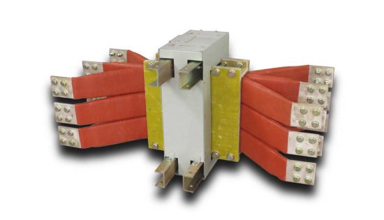
The LJM-1, LJM-2, LJM-3, and LJM-3L series busbar-type zero-sequence current transformers are precision electromagnetic instruments designed for ground fault protection in medium-voltage AC power systems. These transformers are engineered for reliable detection of residual current in three-phase systems, providing critical protection against single line-to-ground faults in generators and motors.

Operating at rated frequencies of 50 Hz or 60 Hz, the LJM series is designed for indoor installation in power systems with rated voltage up to 15 kV (commonly applied in 6 kV, 10 kV, and 15 kV networks). The busbar-type integrated structure provides straightforward installation and robust performance for zero-sequence protection applications.
Key Ratings
| Item | Specification |
|---|---|
| System voltage class | 6 kV, 10 kV, 15 kV (indoor ground fault protection applications) |
| Rated frequency | 50 Hz or 60 Hz |
| Rated secondary current | 5 A |
| Application type | Zero-sequence protection (ground fault detection) |
| Primary conductor | Integrated busbar-type structure (cable-through design) |
| Thermal withstand capability | High thermal withstand suitable for medium-voltage applications |
| Dynamic withstand capability | Robust dynamic withstand for system fault conditions |
| Installation environment | Indoor only (clean, non-corrosive environment) |
| Applicable standards | Q/JB 3380-84 (enterprise standard) |
| Recommended relay | DD11/60 relay for zero-sequence protection coordination |
Working Principle
Zero-sequence current transformers operate on the principle of detecting residual current in three-phase systems. Under normal balanced conditions, the vector sum of three-phase currents is zero, producing no magnetic flux in the transformer core. When a ground fault occurs, unbalanced current (zero-sequence component) flows through the system, generating magnetic flux proportional to the fault current. This flux induces voltage in the secondary winding, producing a standardized output current that activates protective relays when the fault current exceeds preset threshold values.
System Application Position
- Generator Protection: Zero-sequence protection for three-phase AC generators against stator ground faults
- Motor Protection: Ground fault detection for medium-voltage motor installations
- Transformer Neutral Protection: Ground fault monitoring in transformer neutral grounding systems
- Feeder Protection: Cable and overhead line ground fault protection in distribution networks
- Switchgear Integration: Protection coordination with relay systems in 6-15 kV switchgear
Structural Overview
The LJM series features busbar-type construction with integrated primary conductor, enabling direct cable-through installation without external primary connections. The robust mechanical design ensures reliable long-term operation in indoor switchgear environments. When zero-sequence fault current reaches the relay setting value, the transformer outputs accurate secondary current to trigger protective relay operation, providing effective system protection against ground faults.
Industry Applications
The LJM series zero-sequence current transformers serve diverse industrial sectors requiring reliable ground fault protection:
- Power Generation & Distribution: Generator stator protection, substation feeder monitoring, and distribution network ground fault detection
- Petrochemical & Oil & Gas: Refinery motor protection, offshore platform electrical systems, and pipeline cathodic protection monitoring
- Metallurgy & Mining: Steel mill motor drives, mining equipment protection, and heavy industrial machinery ground fault detection
- Railway & Transportation: Electric railway traction systems, subway power distribution, and transportation infrastructure protection
Model Designation

Model Code Explanation
- L — Current transformer (CT)
- J — Ground protection application (zero-sequence detection)
- M — Busbar-type structure (cable-through design)
- 1 / 2 / 3 — Voltage class code and current rating designation
- 3L — Extended rating variant (higher primary current capacity)
Service Conditions
The LJM series zero-sequence current transformers are designed for indoor operation under normal service conditions in medium-voltage power systems.
- Installation environment: Indoor installation only in clean, non-corrosive atmosphere
- Altitude: Standard altitude range with engineering confirmation available for higher elevations
- Ambient temperature: Standard industrial temperature range
- Relative humidity: Suitable for typical indoor industrial environments
- Environmental conditions: Free from corrosive gases, vapors, chemical deposits, explosive or conductive dust; no severe vibration or mechanical shock
Construction
Construction Design
- Structure: Busbar-type configuration with integrated primary conductor
- Core: Ring-type magnetic core optimized for zero-sequence detection
- Insulation: Voltage class-specific insulation system
- System: Cable-through aperture for direct primary conductor installation
- Terminals: Secondary terminal block for relay connection
The busbar-type structure enables straightforward installation by passing three-phase cables or busbars through the transformer aperture. The integrated design eliminates the need for separate primary connections, reducing installation complexity and improving system reliability.
Windings & Terminal Marking
- Primary conductor: Three-phase cables/busbars pass through aperture (no discrete terminals)
- Secondary terminals: K1 / K2 (connection to zero-sequence relay)
- Secondary rated current: 5 A nominal output
Terminal polarity shall be observed during relay connection. Under zero-sequence fault conditions, current flows from K1 to K2, providing proper phase relationship for relay operation. The secondary circuit must remain connected to relay burden during normal operation.
Technical Data
This section provides general technical information for the LJM series busbar-type zero-sequence current transformers designed for 6-15 kV AC systems (50 Hz / 60 Hz). Specific technical parameters are provided on individual product nameplates and datasheets.
General Specifications: Technical parameters including thermal withstand current (Ith), dynamic withstand current (Idyn), and insulation levels are determined based on specific model and application requirements. Detailed technical data is available upon request.
Data Reference
Comprehensive technical data sheets with detailed performance characteristics, test results, and dimensional information are available for each LJM model variant. Contact our technical team for specific application requirements.
Standards & Normative References
| Standard | Title | Application |
|---|---|---|
| Q/JB 3380-84 | Enterprise Standard for Zero-Sequence Current Transformers | Design and performance requirements |
| IEC 61869-1 | Instrument Transformers – Part 1: General Requirements | General CT requirements (reference) |
| IEC 61869-2 | Instrument Transformers – Part 2: Additional Requirements for Current Transformers | CT-specific requirements (reference) |
| GB/T 20840.1 | Instrument Transformers – Part 1: General Requirements | National standard framework |
| GB/T 20840.2 | Instrument Transformers – Part 2: Current Transformers | National CT requirements |
Factory Test Compliance
- Routine tests per applicable Q/JB 3380-84 requirements (polarity verification, ratio verification, insulation resistance)
- Dielectric tests per insulation coordination requirements
- Visual and dimensional inspection including marking and workmanship conformity
- Special tests as required by project specification
Installation Guide
Installation Environments
- Zero-sequence current transformers shall be installed in indoor switchgear or motor control centers with adequate ventilation and protection from environmental contamination.
- Three-phase cables or busbars shall pass through the transformer aperture in the correct sequence to ensure proper zero-sequence detection.
- Secondary terminals shall be securely connected to zero-sequence relay with appropriate wire gauge and termination method.
- Adequate clearance shall be maintained for insulation integrity, heat dissipation, and maintenance access.
Dimensions

LJM-1, LJM-2, LJM-3 (Indoor Type)

LJM-3L (Extended Capacity, Indoor Type)
Safety Precautions During Installation
- Secondary circuit must never be disconnected when primary conductors are energized, as dangerous high voltage may appear across open secondary terminals.
- During inspection or relay testing, the secondary circuit shall be short-circuited before disconnecting relay connections.
- One point of the secondary circuit should be reliably grounded in accordance with applicable standards and project specifications.
- All installation and maintenance work shall comply with local electrical safety regulations and utility requirements.
Customization Options
We offer flexible customization solutions to meet specific project requirements:
- OEM Services: Private labeling, custom packaging, and brand integration for established distributors and system integrators
- ODM Capabilities: Custom design modifications including special voltage ratings, unique mounting configurations, and application-specific features
- International Certifications: Support for global market requirements including regional safety and performance certifications
- Volume Programs: Special pricing and delivery terms for large-scale projects and long-term partnerships
Contact our sales team to discuss your specific customization needs and receive a tailored solution proposal.
Ordering Information
When placing an order, the required configuration shall be specified according to system voltage class, application requirements, and project technical specification. The following parameters shall be clearly stated for technical confirmation and production release:
- System voltage class (6 kV, 10 kV, or 15 kV)
- Application type (generator protection, motor protection, feeder monitoring, etc.)
- Installation environment (standard indoor, special environmental conditions)
- Relay coordination requirements (relay type and interface specifications)
- Special requirements (custom dimensions, unique mounting, additional testing)
If project-specific requirements apply (documentation language, certification requirements, or factory witness testing), specify them at the ordering stage. Special configurations shall be confirmed by technical agreement and final data sheet prior to production.