Product Overview
Functional Definition
The MR series dry-type current transformers are precision electromagnetic instruments designed for accurate current measurement, energy metering, and relay protection applications in low-voltage AC power systems. These transformers utilize electromagnetic induction principles to provide galvanically isolated secondary current signals proportional to primary current, operating at rated frequencies of 50 Hz or 60 Hz.
Key Ratings Snapshot
| Item | Specification (per order / nameplate) |
|---|---|
| System voltage class | 0.66 kV / 0.72 kV (low voltage applications) |
| Rated frequency | 50 Hz or 60 Hz |
| Rated primary current | 30 A to 5000 A |
| Rated secondary current | 1 A or 5 A |
| Accuracy classes | 0.5, 1.0, 3.0 |
| Rated burden | 1 VA to 30 VA (per core/winding as specified) |
| Burden power factor | cosφ = 0.8 (lagging) unless otherwise specified |
| Rated safety factor | FS ≤ 5 |
| Short-circuit withstand | Ith = 60 × Ih (1 s thermal rating) |
| Insulation system | Varnish-treated winding with moisture protection |
| Applicable standards | IEC 60044-1:2003; GB 1208-2006 |
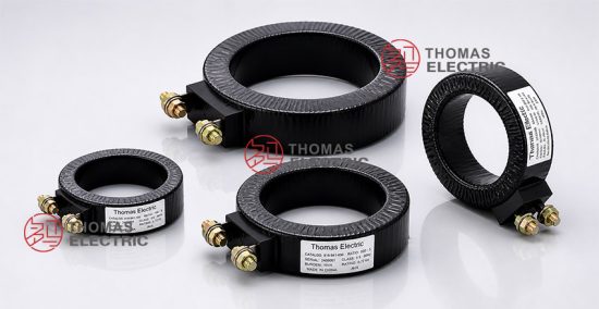
Product Shows


Working Principle
Operating on Faraday’s law of electromagnetic induction, the transformer features a toroidal magnetic core with primary conductor passing through the aperture and secondary windings wound around the core. When primary current flows through the CT, it generates magnetic flux within the core, which induces a proportional current in the secondary winding. The secondary current is scaled down from the primary current, making it suitable for connection to measuring instruments and protection circuits.
System Application Position
- Low Voltage Distribution: 0.4-0.69 kV switchgear and distribution panels
- Energy Metering: Electricity measurement systems for commercial and industrial facilities
- Protection Circuits: Overcurrent and ground fault protection schemes
- Monitoring Systems: Power quality monitoring and load management applications
Structural Form Overview
Fully enclosed plastic housing construction with varnish-treated secondary winding ensures superior moisture resistance and mechanical protection. The window-type (pass-through) mounting configuration provides simple installation by passing the primary conductor through the transformer aperture, eliminating the need for primary winding connections while maintaining excellent electrical isolation.
Model Designation
Model Code Explanation
- M — Metering and measurement application
- R — Window-type (pass-through) construction
The MR designation indicates a window-type current transformer optimized for metering applications in low-voltage power systems, with primary conductor passing directly through the transformer aperture.
Service Conditions
The MR series current transformers are designed for indoor operation under normal service conditions in low-voltage power systems.
- Installation environment: Indoor installation only
- Altitude: Not exceeding 1000 m above sea level (higher altitude requires engineering confirmation)
- Ambient temperature: −5 °C to +40 °C
- Relative humidity: Daily average ≤ 95%, monthly average ≤ 90% (at +20 °C reference)
- Environmental conditions: Free from corrosive gases or vapors; free from explosive or flammable media; no severe vibration, mechanical shock, or impact
Construction
Construction Design
- Structure: Window-type (pass-through) for conductor insertion
- Housing: Fully enclosed plastic enclosure
- Insulation: Varnish-treated secondary winding with moisture protection
- Core: Toroidal magnetic core with optimized permeability
The fully enclosed plastic housing protects against environmental contamination while the varnish-treated winding provides long-term insulation stability and moisture resistance for indoor service environments.
Windings & Terminal Marking
- Primary conductor: Passes through transformer window (no fixed terminals)
- Secondary terminals: K / L (or S1 / S2 per standard marking convention)
Terminal markings follow standard CT polarity conventions. Current flows from K to L (or S1 to S2) when primary current direction is correctly oriented. Proper terminal identification shall be observed to ensure accurate metering and protection performance.
Technical Data
This section provides selection-oriented technical data for the MR series indoor, dry-type current transformer used in low-voltage AC systems (50 Hz or 60 Hz). Data shown below is intended for preliminary selection of primary current rating, accuracy class, and rated burden.
Definitions: Rated primary current is the continuous current rating of the primary conductor. Accuracy class indicates measurement precision under specified burden conditions. Rated output (VA) is the maximum burden the secondary can supply while maintaining rated accuracy. Ith is the rated short-time thermal current (typically 1 s).
Notation: Ith expressed as 60 × Ih indicates thermal withstand capability of 60 times rated primary current for 1 second; acceptance shall be based on nameplate values and factory test report.
Technical Specifications Table
| Rated Primary Current (A) | Rated Secondary Current (A) | Accuracy Class | Rated Output (VA) | Short-time Thermal Current (Ith) |
|---|---|---|---|---|
| 30, 40, 50, 60, 75 | 5 or 1 | 0.5, 1.0, 3.0 | 1, 2.5, 5, 10, 15, 30 | 60 × Ih (1 s) |
| 100, 150, 200, 250, 300 | 5 or 1 | 0.5, 1.0, 3.0 | 1, 2.5, 5, 10, 15, 30 | 60 × Ih (1 s) |
| 400, 500, 600, 750, 800 | 5 or 1 | 0.5, 1.0, 3.0 | 1, 2.5, 5, 10, 15, 30 | 60 × Ih (1 s) |
| 1000, 1200, 1500, 1600 | 5 or 1 | 0.5, 1.0, 3.0 | 1, 2.5, 5, 10, 15, 30 | 60 × Ih (1 s) |
| 2000, 2500, 3000, 4000, 5000 | 5 or 1 | 0.5, 1.0, 3.0 | 1, 2.5, 5, 10, 15, 30 | 60 × Ih (1 s) |
Standards & Normative References
| Standard | Title | Application |
|---|---|---|
| IEC 60044-1:2003 | Instrument Transformers – Part 1: Current Transformers | International standard for current transformer requirements |
| GB 1208-2006 | Current Transformers | National standard (aligned with IEC requirements) |
| IEC 61869-2 | Instrument Transformers – Part 2: Additional Requirements for Current Transformers | Updated CT-specific requirements (replaces IEC 60044-1) |
| GB/T 20840.2 | Instrument Transformers – Part 2: Current Transformers | Updated national CT requirements (aligned with IEC 61869-2) |
Factory Testing Compliance
- Routine tests per applicable IEC/GB requirements (including polarity/marking verification, ratio verification, and accuracy verification per specified class and burden)
- Dielectric tests per insulation requirements and applicable standard
- Visual and dimensional inspection including marking legibility and workmanship conformity
- Type tests and special tests as required by project specification
Installation & Dimensions
Outline Drawing

- Primary conductor passes through the transformer window aperture; conductor size must fit within the specified window dimensions.
- The transformer shall be securely mounted using designated mounting holes or brackets.
- Adequate clearance shall be maintained for heat dissipation and maintenance access.
- Primary conductor orientation determines secondary current polarity; verify terminal marking for correct installation.
Safety Notes
- Secondary circuit shall be short-circuited before disconnecting any connected instruments during maintenance.
- One point of the secondary circuit should be reliably grounded in accordance with applicable standards and local electrical codes.
- All installation and maintenance work shall comply with local electrical safety regulations and utility requirements.
Ordering Information
When placing an order, the required configuration shall be specified according to the local utility requirements, applicable standards, and project technical specification. The following parameters shall be clearly stated for technical confirmation and production release:
- Rated primary current (e.g., 100 A, 500 A, 1000 A)
- Rated secondary current (1 A or 5 A)
- Accuracy class (0.5, 1.0, or 3.0 per application requirements)
- Rated burden (VA) for secondary circuit
- Quantity required and delivery schedule
Selection Procedure
1: Determine rated primary current based on feeder continuous load rating and expected operating current range.
2: Select accuracy class based on application requirements (0.5 for revenue metering, 1.0 for standard measurement, 3.0 for indication purposes).
3: Calculate required rated burden (VA) based on connected meter impedance and secondary wiring resistance.
4: Verify short-circuit withstand capability (Ith = 60 × Ih) meets system fault current requirements.
If special requirements apply (e.g., extended temperature range, enhanced environmental protection, specific terminal configuration, or certification requirements), specify them at the ordering stage for engineering confirmation.
FAQs
Q1: How to select CT ratio and rated primary current for low-voltage applications?
A: Select rated primary current based on feeder continuous load rating, typically 110-120% of maximum expected load current. Verify the selected rating provides adequate measurement range for load variations while avoiding saturation.
Q2: What accuracy class is required for revenue metering vs. general measurement?
A: Revenue metering typically requires Class 0.5 accuracy for billing purposes. Class 1.0 is suitable for standard measurement and monitoring applications. Class 3.0 may be used for indication and non-critical measurements.
Q3: How to determine rated burden (VA) for CT secondary circuits?
A: Rated burden shall cover total connected load including meter impedance and wiring resistance. Calculate burden as: VA = I²× Z, where I is secondary current (1 A or 5 A) and Z is total circuit impedance in ohms.
Q4: Can 1 A secondary current be used instead of 5 A for long cable runs?
A: Yes. 1 A secondary current reduces burden from cable resistance by factor of 25 (5²/1²), making it preferable for installations with long secondary wiring between CT and meter location.
Q5: What is the significance of Ith = 60 × Ih short-circuit rating?
A: Ith rating indicates the transformer can withstand 60 times rated primary current for 1 second without thermal damage. This ensures safe operation during system fault conditions. Verify this rating exceeds maximum prospective fault current at installation location.
Q6: What are the secondary handling and polarity requirements?
A: Never open-circuit CT secondary under energized primary conditions. Short-circuit and ground the secondary before maintenance per standard practice. Observe terminal markings (K/L or S1/S2) for correct polarity to ensure accurate metering direction.
Q7: Which standards govern compliance and certification requirements?
A: MR transformers comply with IEC 60044-1:2003 / IEC 61869-2 and GB 1208-2006 / GB/T 20840.2. Factory test certificates with ratio verification, accuracy verification, and dielectric test results are provided with each unit.
Q8: Can the MR transformer be used with DC current or variable frequency drives?
A: No. The MR transformer is designed for 50 Hz or 60 Hz AC applications only. DC current or non-sinusoidal waveforms (such as VFD outputs) may cause measurement errors and core saturation. Consult factory for specialized requirements.