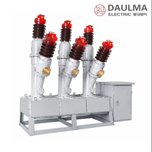
Product Overview
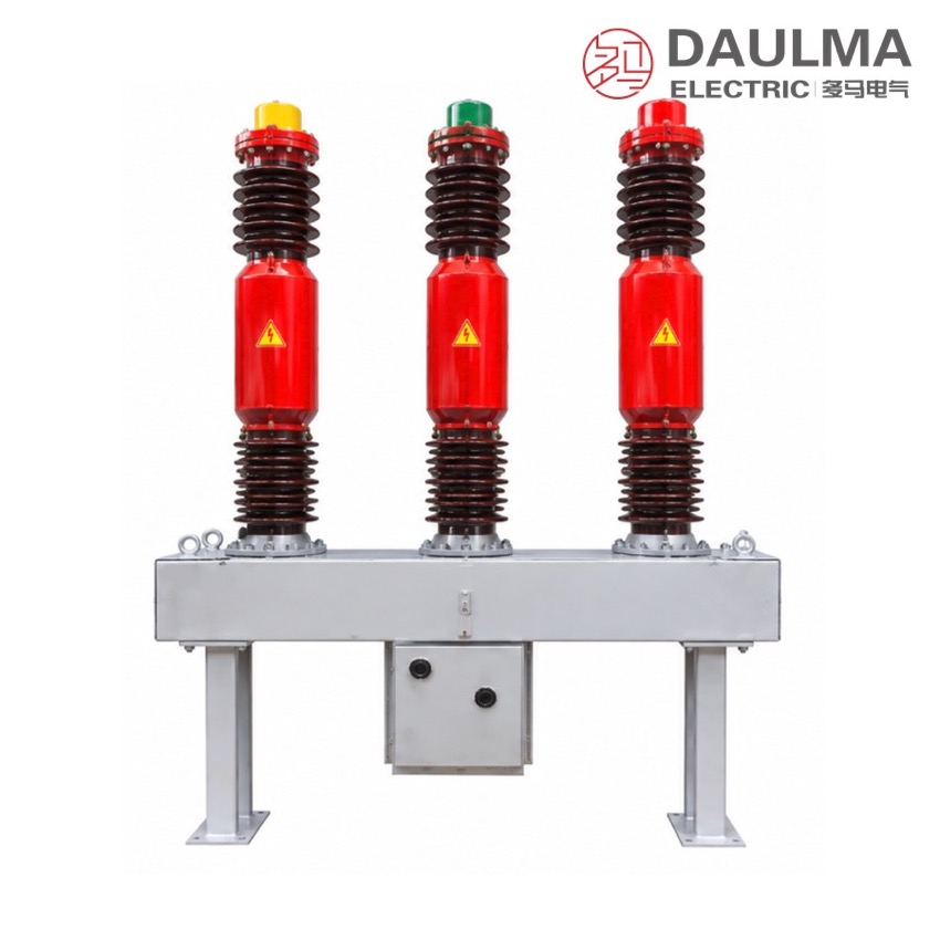
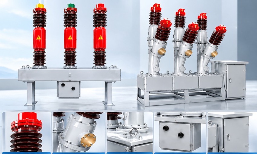
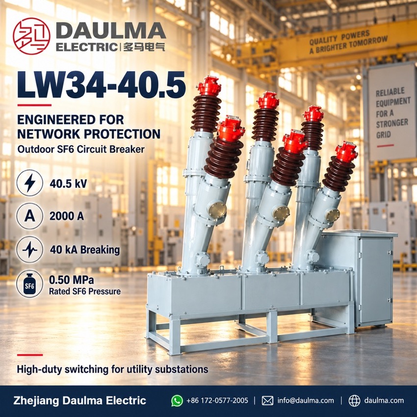
The LW8, LW16, LW34-40.5 and T2000-40 series are outdoor high-voltage AC SF6 circuit breakers designed for three-phase 50Hz systems with a rated voltage of 40.5kV. They provide reliable control and protection for 40.5kV transmission networks and are well-suited for combined breaker and capacitor bank installations, delivering exceptional performance in urban, industrial, rural and substation applications. A compact ceramic column structure integrated with the CT14 spring-operated mechanism offers excellent mechanical reliability with over 3,000 operational cycles; advanced air-compression arc-extinguishing enables up to 12 consecutive breaks at 40kA without maintenance, high-precision current transformers (up to 12 units) support long-distance load lines, and superior sealing keeps the annual SF6 leakage rate below 1%.
Product Display
Model Designation
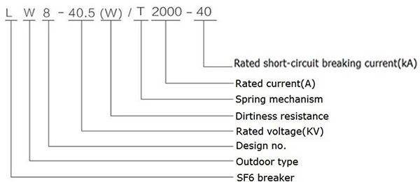
Model format: LW 8/16/34 – 40.5 (W) T 2000 – 40
- L: SF6 Circuit Breaker
- W: Outdoor Installation
- 8 / 16 / 34: Design Sequence Number
- 40.5: Rated Voltage (kV)
- (W): Pollution-Resistant Variant (Optional)
- T: Spring-Operated Mechanism
- 2000: Rated Current (A)
- 40: Rated Short-Circuit Breaking Current (kA)
Service Conditions
- Altitude:
- Ambient Temperature: -30 degC to +45 degC
- Pollution Level:
- Relative Humidity: Daily
- Wind Pressure:
- Daily Temperature Variation:
- Sunlight Intensity:
- Seismic Resistance: Horizontal acceleration
- Ice Coating Thickness:
- Installation Environment: Outdoor only
Construction
The breaker features a vacuum-sealed SF6 chamber with imported V-type dynamic seals incorporating spring pressure compensation to maintain stable gas integrity; terminal markings follow standard conventions with P1/P2 for primary power terminals and S1/S2 for secondary current transformer outputs.
Built-in micro-crystalline alloy current transformers achieve accuracy classes of 0.2 or 0.2S, and an MKZ-type SF6 density monitor provides temperature-compensated pressure readings for simplified maintenance.
Technical Data
| Item | Unit | Data |
|---|---|---|
| Rated Voltage | kV | 40.5 |
| Lightning Impulse Withstand Voltage (Peak) | kV | 185 |
| 1min Power Frequency Withstand Voltage | kV | 95 |
| Rated Current | A | 2000 |
| Mechanical Life | times | 3000 |
| SF6 Gas Rated Pressure (20 degC gauge) | MPa | 0.50 |
| Alarm / Minimum Functional Pressure (20 degC gauge) | MPa | 0.47 / 0.45 |
| Rated Short-Circuit Breaking Current | kA | 40 |
| Rated Short-Circuit Closing Current (Peak) | kA | 100 |
| Rated Short-Time Withstand Current | kA | 40 |
| Rated Peak Withstand Current | kA | 100 |
| Accumulated Breaking Times at Rated Short-Circuit Current | times | 12 |
| Rated Short-Time Duration | s | 4 |
| Closing Time (at rated operating voltage) | s | |
| Opening Time (at rated operating voltage) | s | |
| Rated Operating Sequence | – | O-0.3s-CO-180s-CO |
| Rated Capacitor Switching Current | A | 400 |
| Annual Leakage Rate | % | |
| SF6 Gas Moisture Content (V/V) | – | |
| Rated Operating Voltage (CT14 spring mechanism) | V | AC 220, 380; DC 48, 110, 220 |
| SF6 Gas Weight | kg | 8 |
| Breaker Weight (including mechanism) | kg | 1400 |
Standards
The LW series is designed and type-tested to IEC 62271-100 and GB 1984 for high-voltage alternating-current circuit-breakers, covering insulation level, short-circuit making and breaking, and mechanical endurance.
Installation & Dimensions
Installation Diagram
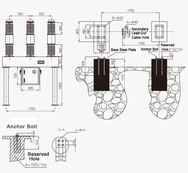
Mount the breaker on a level concrete foundation using the base frame. Ensure adequate clearance around the unit for maintenance and gas handling. All electrical connections must comply with local codes and use the torque specifications provided in the installation manual.