Article Content
11kV Cast-Resin Current Transformer LFS-10 for Metering and Protection – IEC 61869-2 Standard
Introduction to the LFS-10 Current Transformer
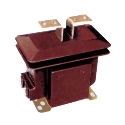
The LFS-10 is a high-voltage, indoor-type cast-resin current transformer (CT) engineered for precise current measurement and dependable protective relay coordination in 11kV (IEC-rated) or 10kV (domestic system) power networks. Designed per IEC 61869-2 and GB/T 20840.2, it leverages vacuum pressure impregnation (VPI) epoxy resin technology to provide superior dielectric strength, environmental resilience, and long-term operational stability. Unlike traditional oil-immersed CTs, the LFS-10 eliminates fire hazards, reduces maintenance overhead, and offers compact integration into metal-clad switchgear and ring main units.
Operating Principle of Cast-Resin Insulation
Cast-resin insulation in the LFS-10 utilizes a two-component epoxy system cured under vacuum and pressure to fully encapsulate the primary conductor, secondary windings, and magnetic core. This process eliminates air voids and moisture ingress pathways, ensuring uniform electric field distribution and preventing partial discharge inception below 10 pC at 1.2 × Um/√3 (where Um = 12 kV). The resin matrix exhibits a relative permittivity (εr) of 3.8–4.2 and volume resistivity exceeding 1×10¹⁴ Ω·cm at 20°C. Thermal conductivity of 0.8–1.0 W/(m·K) enables efficient heat dissipation during continuous or short-time overcurrent events. The solid insulation system maintains mechanical integrity across –40°C to +70°C ambient ranges, making it suitable for unheated indoor substations in temperate and tropical climates.
Advantages Over Oil-Immersed Designs
Compared to oil-filled CTs, the LFS-10’s dry-type construction eliminates flammability risks (meeting IEC 60695 glow-wire ignition test requirements), removes the need for oil sampling or leak monitoring, and reduces weight by 30–40%. Its hermetically sealed structure resists humidity, dust, and chemical contaminants—critical for industrial environments with airborne particulates or corrosive gases. Additionally, the absence of liquid insulation simplifies transportation and installation logistics, as no tilt-angle restrictions apply. The LFS-10 also demonstrates superior seismic performance (tested to 0.5g horizontal acceleration per IEC 60068-2-57), an advantage in earthquake-prone regions where oil-filled units may suffer tank deformation or bushing failure.
Typical Application Overview
The LFS-10 is primarily deployed in 11kV/10kV indoor substations serving commercial complexes, manufacturing plants, data centers, and utility distribution feeders. It interfaces with revenue-class energy meters (Class 0.2S or 0.5S) and protection relays requiring 5P10 or 10P15 accuracy under fault conditions. Common configurations include single-ratio (e.g., 400/5 A) or multi-tap secondary windings (e.g., 200–400–600/5 A) to accommodate load growth. The transformer’s compact footprint (typically 180 mm height × 120 mm diameter) allows side-by-side mounting in 630 A or 1250 A switchgear panels without derating.
Technical Specifications
The LFS-10 adheres to stringent electrical and mechanical parameters defined by IEC 61869-2 and GB/T 20840.2, ensuring interoperability and performance consistency across global markets.
| Parameter | Value |
|---|---|
| Rated Voltage (Ur) | 11 kV (IEC) / 10 kV (GB) |
| Maximum System Voltage (Um) | 12 kV |
| Primary Current Ratings | 50 A to 3000 A (standard); up to 4000 A (custom) |
| Secondary Current | 1 A or 5 A (user-selectable) |
| Metering Accuracy Class | 0.2S, 0.5S (per IEC 61869-2 Table 101) |
| Protection Accuracy Class | 5P10, 5P15, 10P10, 10P15, 10P20 |
| Rated Output (Burden) | 2.5 VA to 30 VA (metering); 15 VA to 50 VA (protection) |
| Short-Time Thermal Current (Ith) | 20 kA for 1 s (standard); 25 kA/1s (optional) |
| Dynamic Withstand Current (Idyn) | 50 kA peak |
| Power Frequency Withstand Voltage | 28 kV rms, 1 min (phase-to-earth) |
| Lightning Impulse Withstand Voltage | 75 kV peak (1.2/50 μs wave) |
| Insulation Material | VPI epoxy resin with silica filler |
| Magnetic Core Material | Grain-Oriented Electrical Steel (GOES), M4 grade |
| Ambient Temperature Range | –40°C to +40°C (storage: –50°C to +70°C) |
| Relative Humidity | ≤95% non-condensing |
| Altitude Limit | ≤1000 m above sea level (derating required >1000 m) |
Accuracy and Burden Characteristics
The LFS-10 achieves metering accuracy class 0.2S with composite error ≤±0.2% at 20–120% of rated primary current and power factor cos φ = 0.8–1.0 lagging. For protection applications, the 5P10 class guarantees composite error ≤±5% at 10× rated current with burden ≤ rated output. Core saturation is suppressed through precise air-gap control and GOES lamination stacking (thickness 0.23 mm), yielding knee-point voltage (Vk) ≥ 150 V for 5P10 windings at 5 A secondary. Burden tolerance is ±10% of declared value; exceeding this may degrade accuracy or cause relay misoperation. Secondary terminals are labeled S1/S2 with reducing polarity (IEC 61869-2 Clause 6.3.2).
Environmental and Mechanical Ratings
Designed for indoor use only, the LFS-10 complies with IP00 enclosure rating but is typically installed within IP4X switchgear compartments. The cast-resin housing withstands UV exposure during temporary outdoor storage but must be shielded from direct sunlight during operation to prevent surface cracking. Mounting is via M10 threaded inserts on the base flange, compatible with standard DIN 43673 brackets. Vibration resistance meets IEC 60068-2-6 (10–150 Hz, 0.5 mm amplitude). At altitudes above 1000 m, the power frequency withstand voltage must be reduced by 1% per 100 m increment per IEC 60071-2.
Typical Applications
The LFS-10 serves diverse roles in medium-voltage infrastructure where reliability, accuracy, and space efficiency are paramount.
Substation Secondary Metering
In utility-owned 11kV/0.4kV distribution substations, the LFS-10 provides revenue-grade current signals to AMI (Advanced Metering Infrastructure) systems. Paired with 0.2S-class meters, it ensures billing accuracy within ±0.2% across seasonal load variations—from light nighttime loads (5% In) to peak summer demand (100% In). Its low phase displacement error (<±10 minutes at 100% In) prevents reactive energy miscalculation. The transformer’s thermal stability minimizes drift over 25+ years, reducing recalibration frequency compared to older wound-core designs.
Industrial Power Distribution
Within factory switchyards, the LFS-10 monitors motor feeder currents (e.g., 630 A circuits driving 500 kW induction motors) and supplies inputs to multifunction protection relays (e.g., Siemens 7SJ62). The 10P15 protection winding ensures reliable tripping during bolted three-phase faults (up to 15× rated current) while maintaining sufficient excitation margin to avoid saturation during motor start-up inrush (typically 6–8× In for 5–10 seconds). Its compact size enables retrofitting into legacy MCC (Motor Control Center) panels without busbar modifications.
Renewable Energy Integration
Solar PV and wind farm collector substations utilize the LFS-10 to interface inverters or turbines with SCADA systems and anti-islanding protection schemes. Bidirectional current flow during grid export/import is handled without accuracy degradation due to symmetrical core design. The CT’s fast response time (<20 ms to 90% steady-state output after fault inception) supports rapid disconnection per IEEE 1547 requirements. In microgrid applications, its 5P10 winding feeds differential relays protecting step-up transformers against internal faults.
Rural and Suburban Distribution Networks
For rural electrification projects, the LFS-10’s maintenance-free operation reduces lifecycle costs in remote locations with limited technician access. Installed in pole-mounted or pad-mounted switchgear, it supports load profiling for demand-side management and detects high-impedance faults via sensitive earth-fault relays (using residual connection of three CTs). Its robust insulation withstands transient overvoltages from lightning-induced surges on overhead lines, validated by 75 kV BIL (Basic Impulse Level) testing.
Compliance with International Standards
The LFS-10’s design, testing, and certification strictly follow IEC 61869-2 (Instrument transformers – Part 2: Additional requirements for current transformers) and its Chinese counterpart GB/T 20840.2.
IEC 61869-2 Compliance Details
Per IEC 61869-2, the LFS-10 undergoes type tests including temperature rise (≤60 K for windings at 1.2× In), short-circuit withstand (20 kA/1s without damage), and accuracy verification across 1–120% In. Partial discharge measurements are conducted at 1.2 × Um/√3 = 8.3 kV, with inception levels <5 pC. The standard mandates that protection CTs maintain specified accuracy up to the rated symmetrical short-circuit current factor (e.g., 10 for 5P10). The LFS-10 exceeds this with a measured accuracy limit factor (ALF) of 12.5 at 25°C ambient, verified using the indirect method (IEC 61869-2 Annex D).
Alignment with GB/T 20840.2
GB/T 20840.2 mirrors IEC 61869-2 but includes supplementary requirements for Chinese grid operators. Key additions include mandatory salt fog testing (96 hours, 5% NaCl solution) for coastal installations and stricter vibration criteria (0.3g RMS from 10–55 Hz). The LFS-10’s resin formulation incorporates hydrophobic additives to pass these tests without coating. Domestic standards also specify 10kV as the nominal system voltage (vs. 11kV IEC), though insulation levels remain identical (Um = 12 kV). All LFS-10 units shipped to China carry CQC (China Quality Certification) marks alongside CE.
Testing and Certification Protocols
Certification requires witnessed type testing at accredited labs (e.g., KEMA, CESI, or SGCC). Routine tests per IEC 61869-2 Clause 10 include power frequency withstand (28 kV/1 min), turns ratio verification (±0.5% tolerance), and polarity check. Sample tests (per batch) cover partial discharge and temperature rise. The LFS-10’s production line implements statistical process control (SPC) for core permeability and resin viscosity, ensuring batch-to-batch consistency. Test reports include oscillograms of short-circuit current waveforms and thermal imaging during overload cycles.
On-Site Testing Procedures
Post-installation verification ensures the LFS-10 performs within specifications before energization.
Insulation Resistance Test
Using a 2500 V DC megohmmeter, measure insulation resistance between primary-to-secondary, primary-to-ground, and secondary-to-ground. Acceptance criterion: ≥1000 MΩ at 20°C. Correct for temperature using RT2 = RT1 × 2(T1–T2)/10. Low readings indicate moisture ingress or resin cracking—requiring drying or replacement. Perform before and after power frequency withstand tests to detect insulation degradation.
Turns Ratio Test
Apply 1–5 V AC at 50 Hz to the secondary winding and measure induced primary voltage (open-circuit primary). Calculate ratio as Vp/Vs; compare to nameplate (e.g., 400/5 = 80:1). Tolerance: ±0.5% for metering, ±1.0% for protection windings. Alternatively, use a dedicated CT analyzer injecting 1–10 A primary current and measuring secondary output. Deviations >1% suggest inter-turn shorts or incorrect tap selection.
Polarity Test
Verify reducing polarity per IEC 61869-2 Figure 3. Connect a 1.5 V battery between P1 (+) and P2 (–). Momentarily close the circuit while monitoring a DC millivoltmeter across S1 (+) and S2 (–). A positive kick confirms correct polarity. Incorrect polarity causes watt-hour meters to register reverse energy and protection relays to misoperate during external faults. Document results with timestamped oscillograms.
Power Frequency Withstand Voltage Test
Apply 28 kV rms at 50 Hz between primary and grounded secondary/core for 1 minute. Use a calibrated HV test set with automatic trip at 10 mA leakage current. The unit must withstand without flashover, excessive noise, or >5% voltage drop. Conduct at 80% humidity; if failed, inspect for surface contamination or internal voids via ultrasonic testing.
Short-Circuit Test (for CT)
Inject 10× rated primary current (e.g., 4000 A for 400/5 A CT) into the primary with secondary short-circuited. Measure secondary current and calculate composite error: |(KnIs – Ip)/Ip| × 100%, where Kn = nominal ratio. For 5P10, error must be ≤5%. Monitor core temperature rise with IR camera; ΔT ≤15 K after 10 seconds indicates adequate thermal design. This test validates performance under fault conditions.
Preventive Maintenance Guide
Although cast-resin CTs require minimal upkeep, scheduled inspections extend service life beyond 30 years.
Periodic Inspection Protocol
Annually, perform visual checks for resin discoloration (indicating thermal aging), terminal corrosion, or tracking marks. Clean surfaces with isopropyl alcohol; never use abrasive cleaners. Verify torque on secondary terminal screws (2.5 N·m for M4 brass). Measure insulation resistance biennially; a 50% drop from baseline warrants further investigation. In high-pollution areas (e.g., cement plants), inspect every 6 months for conductive dust accumulation on bushings.
Maintenance Intervals and Fault Diagnosis
Replace the LFS-10 if any of the following occur: insulation resistance <100 MΩ, ratio error >2%, or audible humming under load (signaling core lamination looseness). After severe fault interruption (>15 kA), conduct dissolved gas analysis (DGA) is unnecessary (no oil), but perform partial discharge mapping to detect new voids. The table below summarizes key intervals:
| Activity | Frequency | Acceptance Criteria |
|---|---|---|
| Visual Inspection | Annual | No cracks, burns, or deposits |
| Insulation Resistance | Biennial | ≥1000 MΩ @ 20°C |
| Ratio & Polarity | After major fault | Within ±1% tolerance |
| Thermal Imaging | Every 5 years | ΔT ≤10 K vs. adjacent CTs |
Conclusion
The LFS-10 11kV cast-resin current transformer represents a benchmark in medium-voltage instrumentation, combining IEC 61869-2-certified accuracy with rugged, maintenance-free construction. Its VPI epoxy resin insulation and GOES core deliver exceptional dielectric strength, thermal stability, and magnetic linearity—critical for both revenue metering (0.2S/0.5S) and high-reliability protection (5P/10P). By eliminating oil-related hazards and enabling compact switchgear integration, the LFS-10 reduces total cost of ownership while meeting stringent global standards including GB/T 20840.2. Field-proven in utilities, industry, and renewables, it offers a service life exceeding 25–30 years with minimal intervention. Engineers selecting the LFS-10 gain a future-proof solution that adapts to evolving grid demands—from smart metering to distributed generation—without compromising safety or precision. Its rigorous type testing, traceable calibration, and adherence to international norms ensure seamless interoperability in modern power systems worldwide.