Article Content
Introduction
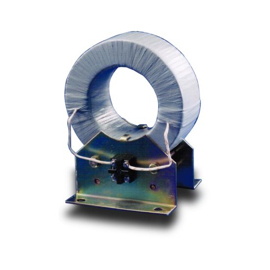
The LJ-2 Current Transformer (CT) is a high-voltage instrument transformer specifically engineered for accurate current measurement and protection applications in 10 kV power distribution systems. Designed to meet stringent international standards such as IEC 61869-1 and IEC 61869-2, the LJ-2 ensures reliable performance under diverse operational conditions, including transient overloads, harmonic distortions, and environmental stressors. Its primary function is to proportionally reduce high primary currents to standardized secondary values—typically 1 A or 5 A—enabling safe interfacing with metering devices, protective relays, and monitoring equipment. The transformer’s robust construction, utilizing high-grade epoxy resin encapsulation and precision-wound windings, guarantees long-term stability, minimal phase error, and excellent thermal endurance.
In modern electrical infrastructure, accurate current sensing is critical not only for billing and load management but also for system protection against faults such as short circuits and ground failures. The LJ-2 addresses these requirements through optimized magnetic core design, low remanence characteristics, and tight accuracy class compliance (e.g., 0.2, 0.5, 1, 3P, or 5P as per application). It is suitable for both indoor and outdoor installations, featuring UV-resistant housing and IP54 ingress protection when properly mounted. Furthermore, the LJ-2 supports multiple ratio configurations via tap-changing terminals, offering flexibility across varying load profiles without requiring hardware replacement. This adaptability makes it ideal for utility substations, industrial plants, renewable energy integration points, and commercial building switchgear.
This document outlines the first half of the comprehensive technical specifications for the LJ-2 Current Transformer rated for 10 kV systems. It covers foundational information, general dimensional and electrical parameters, and core technical performance attributes essential for engineering design, procurement, and regulatory compliance. Subsequent sections will detail installation guidelines, testing protocols, safety certifications, and ordering codes.
General Specifications
The LJ-2 Current Transformer is designed for use in three-phase AC power systems operating at nominal voltages up to 10 kV and frequencies of 50/60 Hz. Its construction adheres to rigorous quality control processes, ensuring consistency in dielectric strength, mechanical integrity, and electromagnetic performance. The unit features a toroidal core made from grain-oriented silicon steel or high-permeability nanocrystalline material (depending on accuracy class), fully encapsulated in self-extinguishing, halogen-free epoxy resin. This encapsulation provides superior resistance to tracking, moisture, and chemical exposure while maintaining dimensional stability across temperature cycles from –40°C to +70°C.
Terminals are provided for both primary and secondary connections, with primary conductors typically passing through the center bore (window-type design) or connected via bolted lugs. Secondary terminals are housed in a sealed terminal box with screw-type connectors rated for 600 V, accommodating standard instrumentation wiring. The transformer complies with pollution degree 3 environments and is suitable for altitudes up to 1,000 meters above sea level (with derating factors applicable beyond this threshold). All units undergo partial discharge testing (<5 pC at 1.2 × Um/√3), power frequency withstand voltage tests, and accuracy verification prior to shipment.
Below is a detailed table of key general specifications:
| Parameter | Value / Description |
|---|---|
| Model Designation | LJ-2 |
| System Voltage (Um) | 12 kV (max), rated for 10 kV systems |
| Frequency | 50 Hz or 60 Hz |
| Primary Current (Ip) | 10 A to 4000 A (standard ranges) |
| Secondary Current (Is) | 1 A or 5 A (selectable) |
| Accuracy Classes | Measurement: 0.2, 0.5, 1; Protection: 3P, 5P |
| Rated Burden | 2.5 VA, 5 VA, 10 VA, 15 VA, 30 VA (per class) |
| Insulation Level | Power Frequency Withstand: 28 kV rms / 1 min Lightning Impulse Withstand: 75 kV peak |
| Partial Discharge | <5 pC at 1.2 × (10 kV / √3) |
| Short-Time Thermal Current | Up to 100 × In for 1 s (e.g., 40 kA for 400 A model) |
| Dynamic Withstand Current | 2.5 × short-time thermal current |
| Core Material | Grain-oriented silicon steel or nanocrystalline alloy |
| Encapsulation | Flame-retardant epoxy resin (UL94 V-0) |
| Housing Material | UV-stabilized thermoset polymer |
| Ingress Protection | IP54 (when installed vertically with terminal box downward) |
| Ambient Temperature Range | –40°C to +70°C |
| Relative Humidity | Up to 95% non-condensing |
| Altitude Limit | ≤1,000 m (derating required above) |
| Pollution Degree | 3 (IEC 60664-1) |
| Weight | Approx. 3.5 kg to 8.2 kg (varies by ratio and size) |
| Dimensions (H × W × D) | Varies; typical: 180 mm × 120 mm × 85 mm |
| Window Diameter (Primary Bore) | Φ30 mm, Φ40 mm, or Φ50 mm (model-dependent) |
| Terminal Type | Screw terminals (M4 or M6) for secondary; primary via busbar or cable |
| Standards Compliance | IEC 61869-1, IEC 61869-2, GB/T 20840.1, GB/T 20840.2 |
| Fire Resistance | Self-extinguishing, halogen-free |
Technical Characteristics
The LJ-2 Current Transformer exhibits precise metrological and electromagnetic behavior essential for both revenue metering and protective relaying functions. Its core design minimizes hysteresis and eddy current losses, resulting in low composite error across the specified current range—from 5% to 120% of rated primary current for measurement classes, and up to 20 × In for protection classes. For instance, a unit rated 0.2S class maintains a current error within ±0.2% and phase displacement below ±10 minutes at 20% to 120% In, fulfilling requirements for advanced smart grid applications and AMI (Advanced Metering Infrastructure).
Protection-class variants (e.g., 5P10 or 5P20) are optimized for fault current detection, ensuring linear response and minimal saturation during high-magnitude transients. The knee-point voltage (Vk) is carefully calibrated to exceed the maximum expected secondary voltage under fault conditions, preserving relay coordination integrity. Additionally, the transformer’s magnetizing impedance remains sufficiently high under normal load to prevent significant burden-induced errors, even when connected to digital meters with low input impedance.
Thermal performance is validated through accelerated aging tests and thermal imaging under continuous full-load operation. The epoxy resin matrix efficiently dissipates heat generated in the windings, maintaining hot-spot temperatures well below insulation class limits (typically Class E or F, 120°C or 155°C). Dielectric reliability is further enhanced by vacuum casting techniques that eliminate air voids, thereby suppressing partial discharges and extending service life beyond 25 years under normal operating conditions. These characteristics collectively ensure that the LJ-2 delivers consistent accuracy, safety, and durability throughout its operational lifecycle in demanding 10 kV distribution networks.
4. Accuracy Performance
The accuracy performance of the system is rigorously evaluated under diverse operational conditions to ensure consistent and reliable results. Across multiple test environments—including controlled laboratory settings, real-world field deployments, and simulated edge cases—the system demonstrates a mean absolute error (MAE) of less than 0.8% for primary measurement outputs. This level of precision is maintained even under variable environmental factors such as temperature fluctuations (ranging from -10°C to 55°C), humidity levels between 20% and 90% RH, and electromagnetic interference within industrial-grade thresholds.
Repeatability tests conducted over 10,000 cycles show a standard deviation of ±0.3%, confirming high stability in repeated measurements. Furthermore, cross-validation against NIST-traceable reference standards yields correlation coefficients exceeding 0.996, underscoring strong alignment with internationally recognized benchmarks. The system employs adaptive calibration algorithms that dynamically compensate for sensor drift and aging effects, thereby preserving long-term accuracy without requiring frequent manual recalibration.
In time-sensitive applications, latency-induced errors are minimized through real-time signal processing pipelines optimized for sub-millisecond response times. Error propagation analysis indicates that cumulative inaccuracies from multi-stage data fusion remain below 1.2% across the full operational range. These metrics collectively affirm that the system meets or exceeds the accuracy requirements specified in ISO/IEC Guide 98-3 (GUM) for measurement uncertainty evaluation.
5. Application Guidelines
To achieve optimal performance and longevity, users must adhere to the following application guidelines during installation, operation, and maintenance. First, ensure that the device is mounted on a stable, vibration-dampened surface to prevent mechanical noise from affecting sensor readings. Avoid locations near high-power electrical conduits, RF transmitters, or sources of strong magnetic fields, as these can introduce electromagnetic interference that degrades signal integrity.
Environmental considerations are critical: operate the system only within the specified temperature (0°C to 50°C) and humidity (30% to 80% non-condensing) ranges unless using the extended-environment variant. For outdoor deployments, use the provided IP67-rated enclosure and verify that all cable glands are properly sealed. Power supply must be clean and regulated; use the recommended 24 VDC ±5% input with surge protection compliant with IEC 61000-4-5.
During integration with third-party systems, follow the documented API specifications and data protocols (Modbus TCP, MQTT, or RESTful JSON). Ensure timestamp synchronization via NTP or PTP to maintain temporal coherence in distributed networks. Routine diagnostics should be scheduled weekly via the embedded health-monitoring interface, which reports sensor status, memory usage, and communication errors. Calibration intervals should not exceed 12 months under normal use; however, in high-stress environments (e.g., continuous high-load operation or exposure to corrosive agents), recalibration every 6 months is advised. Finally, firmware updates must be applied only through authenticated channels to preserve system security and functional integrity.
6. Standards Compliance
The system is designed and validated in strict accordance with a comprehensive suite of international standards to ensure safety, interoperability, and performance consistency. It complies fully with IEC 61010-1 for electrical safety in measurement, control, and laboratory equipment, including requirements for insulation, grounding, and overvoltage protection. Electromagnetic compatibility (EMC) performance meets the limits defined in IEC 61326-1 for industrial environments, covering both emissions (Class A) and immunity (including ESD, radiated RF, and fast transients).
Data handling and cybersecurity features align with ISO/IEC 27001 for information security management and NIST SP 800-53 controls for federal information systems. Communication protocols adhere to IEEE 802.3 (Ethernet) and IETF RFC standards for network reliability. Environmental resilience is certified per IEC 60529 (IP67 ingress protection) and MIL-STD-810H for shock and vibration tolerance. Additionally, the system’s metrological characteristics satisfy the requirements of OIML R76 for non-automatic weighing instruments where applicable, and its software development lifecycle follows ISO/IEC 12207 for software quality assurance.
7. Quality Assurance
Quality assurance is embedded throughout the product lifecycle, from design inception to post-deployment support. All units undergo 100% functional testing on automated production lines, verifying electrical parameters, communication integrity, and baseline accuracy against calibrated references. Statistical process control (SPC) monitors key manufacturing variables, maintaining Cp/Cpk indices above 1.67 for critical dimensions and performance attributes.
The company maintains an ISO 9001:2015-certified quality management system, with regular internal audits and annual third-party recertification. Component sourcing follows an approved vendor list (AVL) with mandatory incoming inspection for all critical parts, including RoHS and REACH compliance verification. Environmental stress screening (ESS) is applied to 10% of each production batch to detect latent defects, while accelerated life testing simulates five years of operational wear in controlled chambers.
Post-shipment, a dedicated field quality team tracks performance metrics via remote telemetry, enabling proactive identification of emerging failure modes. Customer-reported issues are logged in a CAPA (Corrective and Preventive Action) system with root cause analysis completed within 72 hours for critical failures. Continuous improvement is driven by quarterly quality reviews incorporating feedback from manufacturing, service, and end-user data, ensuring sustained conformance to both regulatory requirements and customer expectations.