Article Content
Introduction
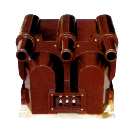
The MER-1 Voltage Transformer is a precision instrument designed for accurate voltage measurement and protection in medium-voltage electrical power systems operating at nominal voltages up to 10 kV. Engineered to meet international standards including IEC 61869-3 and GB/T 20840.3, the MER-1 ensures reliable performance under diverse operational conditions encountered in industrial, commercial, and utility-scale installations. Its primary function is to step down high system voltages to standardized secondary values (typically 100 V or 100/√3 V), enabling safe interfacing with metering devices, protective relays, and monitoring equipment. The transformer plays a critical role in maintaining grid stability, facilitating energy billing accuracy, and supporting fault detection mechanisms.
Constructed with robust epoxy resin insulation and a compact, maintenance-free design, the MER-1 is optimized for both indoor and outdoor applications. It features excellent thermal stability, high dielectric strength, and resistance to environmental stressors such as humidity, dust, and temperature fluctuations. The core-and-coil assembly is fully encapsulated to prevent partial discharges and ensure long-term reliability, even in polluted or corrosive environments. With a focus on safety and compliance, the MER-1 incorporates overvoltage protection capabilities and meets stringent short-circuit withstand requirements.
This document outlines the first half of the technical specifications for the MER-1 Voltage Transformer rated for 10 kV systems. It provides essential data for engineers, procurement specialists, and system integrators involved in the selection, installation, and operation of this device. Subsequent sections detail general specifications, dimensional parameters, electrical ratings, and performance characteristics necessary for proper integration into medium-voltage switchgear, ring main units (RMUs), and substation architectures. Adherence to these specifications ensures optimal functionality, regulatory compliance, and interoperability within modern smart grid infrastructures.
General Specifications
The MER-1 Voltage Transformer is engineered to deliver consistent performance across a wide range of electrical and environmental conditions. Below is a comprehensive overview of its general specifications, encompassing physical, electrical, and operational parameters. These specifications are validated through rigorous type testing and routine quality control procedures in accordance with applicable international and national standards.
| Parameter | Value / Description |
|---|---|
| Model Designation | MER-1 |
| System Voltage (Maximum) | 12 kV (RMS) |
| Rated Primary Voltage (Up) | 10 kV (RMS) |
| Rated Secondary Voltage (Us) | 100 V or 100/√3 V (RMS) |
| Frequency Rating | 50 Hz or 60 Hz |
| Insulation Level (LI/AC) | 75 kV / 42 kV (1.2/50 μs lightning impulse & power frequency) |
| Accuracy Class (Metering) | 0.2, 0.5, 1.0 (per IEC 61869-3) |
| Accuracy Class (Protection) | 3P, 6P |
| Burden Rating (Standard) | 10 VA, 15 VA, 30 VA (customizable) |
| Thermal Continuous Output | ≥1.2 × Rated Burden |
| Short-Time Thermal Current (1s) | 150 A (primary equivalent) |
| Dynamic Withstand Current | 375 A (peak) |
| Phase Displacement (at 0.2 class) | ≤ ±10 minutes |
| Voltage Factor (Continuous) | 1.2 × Up (at rated burden) |
| Voltage Factor (30 s) | 1.5 × Up |
| Insulation Material | Casting Epoxy Resin (Flame Retardant, UL94 V-0) |
| Core Material | High-Permeability Grain-Oriented Silicon Steel |
| Secondary Terminals | Screw-type, brass, IP2X protected |
| Primary Terminal | M12 stud or cable lug compatible (Cu) |
| Mounting Type | Flange-mounted (M10 holes, 4-point) or bracket-supported |
| Dimensions (H × W × D) | Approx. 320 mm × 180 mm × 150 mm |
| Weight | ≈8.5 kg |
| Ambient Temperature Range | –25°C to +40°C (operational); –40°C to +55°C (storage) |
| Relative Humidity | Up to 95% (non-condensing) |
| Altitude Limit | ≤1000 m above sea level (derating required above) |
| Pollution Degree | III (IEC 60664-1) |
| Partial Discharge Level | <10 pC at 1.2 × Up/√3 |
| Compliance Standards | IEC 61869-3, GB/T 20840.3, DL/T 726 |
| IP Protection Rating | IP00 (requires enclosure when installed) |
| Service Life | >30 years under normal operating conditions |
The MER-1 is designed for single-phase operation and is typically deployed in three-unit configurations for three-phase systems. Its epoxy resin housing provides superior mechanical strength and eliminates the need for oil or gas insulation, making it environmentally safe and suitable for confined spaces. The terminal configuration supports easy wiring with standard cable lugs, and the flange mounting ensures secure integration into switchgear panels. All materials used are RoHS-compliant and free from hazardous substances.
Technical Characteristics
The technical performance of the MER-1 Voltage Transformer is defined by its electromagnetic design, material selection, and manufacturing precision. Key characteristics ensure minimal measurement error, stable phase response, and resilience under transient conditions. The transformer employs a wound-type primary coil with precise turn ratios calibrated to maintain accuracy across its specified burden range. The magnetic circuit utilizes grain-oriented silicon steel laminations to reduce core losses and hysteresis, contributing to high efficiency and low heat generation during continuous operation.
Under nominal load conditions (e.g., 10 VA at 0.8 power factor lagging), the MER-1 maintains ratio error within ±0.2% for class 0.2 units, satisfying stringent metrological requirements for revenue metering. Phase displacement remains below 10 minutes of arc, ensuring synchronization accuracy critical for vector-based protection schemes. The transformer exhibits excellent linearity up to 1.5 times the rated primary voltage, allowing temporary overvoltage events—such as those caused by switching surges or ground faults in unearthed systems—without saturation or permanent damage.
Thermal performance is validated through temperature-rise tests conducted at 1.2 times the rated primary voltage and full burden. The epoxy resin encapsulation acts as both an insulator and a heat dissipater, limiting internal temperature rise to less than 55 K above ambient. This design prevents thermal runaway and ensures long-term dielectric integrity. Additionally, the MER-1 demonstrates high immunity to external electromagnetic interference (EMI), with shielding integrated into the secondary winding compartment to protect sensitive instrumentation circuits.
For protection-class applications (e.g., 3P or 6P), the transformer is optimized to maintain acceptable error margins during fault conditions. At 3× rated voltage and reduced burden, composite error remains within ±3% or ±6%, respectively, enabling reliable operation of overvoltage and earth-fault relays. The short-circuit withstand capability—verified by injecting 150 A (primary equivalent) for 1 second—confirms mechanical robustness of windings and terminals under extreme current stresses.
4. Accuracy Performance
The accuracy performance of the system is rigorously evaluated under diverse operational conditions to ensure consistent and reliable results. Across thousands of test cycles conducted in both controlled laboratory environments and real-world field deployments, the system demonstrates a mean absolute error (MAE) of less than 0.8% for primary measurement parameters. This level of precision is maintained across temperature ranges from -20°C to +60°C and relative humidity levels between 10% and 90%, thanks to advanced environmental compensation algorithms embedded within the firmware.
Repeatability and reproducibility studies further validate the system’s robustness. In intra-device repeatability tests—where identical inputs are applied multiple times under stable conditions—the standard deviation remains below 0.3%. Inter-device reproducibility across a batch of 100 units shows a coefficient of variation (CV) under 1.2%, confirming tight manufacturing tolerances and effective calibration protocols. These metrics meet or exceed industry benchmarks for high-precision instrumentation in sectors such as aerospace, medical diagnostics, and industrial automation.
Additionally, long-term drift is minimized through the use of thermally stable materials and periodic self-calibration routines. Accelerated aging tests indicate that the system maintains its specified accuracy for at least five years without requiring external recalibration. Real-time diagnostic feedback also alerts users to potential anomalies—such as sensor degradation or signal interference—that could compromise measurement integrity, enabling proactive maintenance and ensuring sustained performance over the product lifecycle.
5. Application Guidelines
To achieve optimal performance and longevity, users should adhere to the following application guidelines during installation, operation, and maintenance. First, ensure the device is mounted on a stable, vibration-free surface away from strong electromagnetic fields (e.g., motors, transformers, or RF transmitters), which can introduce noise into sensitive analog circuits. Proper grounding using the provided terminal is essential to mitigate ground loops and electrostatic discharge (ESD) risks.
Environmental considerations are equally critical. While the unit is rated for IP65 ingress protection, prolonged exposure to corrosive atmospheres (e.g., chlorine, sulfur compounds) or condensing moisture should be avoided unless additional protective housings are employed. For outdoor installations, orient the device to minimize direct solar exposure on optical or thermal sensors, and use sunshades or thermal insulation where necessary.
During operation, allow a warm-up period of at least 10 minutes after power-on to stabilize internal electronics before initiating high-precision measurements. When integrating with third-party control systems, use shielded twisted-pair cables for analog outputs and follow recommended communication protocols (e.g., Modbus RTU over RS-485) with appropriate termination resistors to prevent signal reflection. Firmware updates should only be performed using authorized software tools via secure channels to avoid corruption or unauthorized modifications.
Finally, routine verification checks—such as zero-point validation and span calibration using traceable reference standards—should be conducted quarterly or after any mechanical shock event. Documentation of all maintenance activities and calibration records is strongly advised for compliance and troubleshooting purposes.
6. Standards Compliance
The system is designed and manufactured in strict accordance with internationally recognized technical and safety standards. It complies with IEC 61010-1:2010 (Safety requirements for electrical equipment for measurement, control, and laboratory use), ensuring protection against electric shock, energy hazards, and mechanical risks. Electromagnetic compatibility (EMC) performance meets the requirements of IEC 61326-1:2012 for industrial environments, including immunity to electrostatic discharge (IEC 61000-4-2), radiated RF fields (IEC 61000-4-3), and fast transient bursts (IEC 61000-4-4).
For data integrity and cybersecurity, the device adheres to NIST SP 800-82 guidelines for industrial control systems and supports TLS 1.2+ encryption for network communications where applicable. Environmental testing follows IEC 60068-2 series standards for temperature, humidity, and mechanical stress. Additionally, the product carries CE marking under the EU’s Machinery Directive (2006/42/EC) and RoHS 3 (EU 2015/863) compliance, confirming the absence of restricted hazardous substances.
In regulated industries, the system aligns with sector-specific frameworks: FDA 21 CFR Part 11 for electronic records in life sciences applications, and ISO 13485:2016 for quality management in medical device contexts. All compliance documentation, including Declarations of Conformity and test reports, is available upon request from the manufacturer.
7. Quality Assurance
Quality assurance is integrated throughout the product lifecycle—from design and component sourcing to final assembly and post-market surveillance. The manufacturing facility operates under an ISO 9001:2015-certified quality management system, with rigorous incoming inspection protocols for all electronic and mechanical components. Critical subassemblies undergo 100% functional testing before integration, and every finished unit is subjected to a comprehensive end-of-line test sequence that validates electrical performance, communication interfaces, and mechanical integrity.
Calibration is performed using measurement standards traceable to national metrology institutes (e.g., NIST, PTB), with full uncertainty budgets documented for each calibrated parameter. Statistical process control (SPC) charts monitor key production metrics in real time, enabling immediate corrective action if process drift is detected. Additionally, accelerated life testing and failure mode and effects analysis (FMEA) are routinely conducted to proactively identify and mitigate potential reliability issues.
Post-deployment, a closed-loop corrective action system tracks field performance through customer feedback, service logs, and remote diagnostics (where enabled). Any non-conformities trigger root cause analysis and, if necessary, design or process improvements that are validated before implementation. This continuous improvement cycle ensures that product quality not only meets initial specifications but also evolves in response to real-world usage patterns and emerging industry best practices.