Article Content
11kV Cast-Resin Voltage Transformer SZV-10R for Metering and Protection – IEC 61869-3 Standard
Introduction to the SZV-10R Voltage Transformer
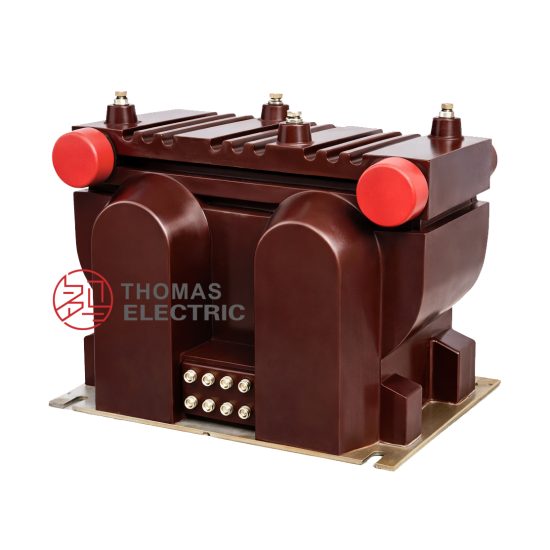
The SZV-10R is a single-phase, indoor/outdoor-rated cast-resin insulated voltage transformer (VT) designed for high-precision metering and reliable protection functions in medium-voltage power systems operating at nominal system voltages of 11kV (IEC standard) or 10kV (domestic Chinese grid equivalent). This instrument transformer leverages vacuum pressure impregnation (VPI) epoxy resin technology to encapsulate its magnetic core and windings, providing superior dielectric strength, mechanical robustness, and environmental resilience compared to traditional oil-immersed alternatives.
Operating Principle of Cast-Resin Insulation
Cast-resin insulation in the SZV-10R employs a two-component cycloaliphatic epoxy resin system cured under controlled temperature and vacuum conditions. This process eliminates air voids and moisture ingress pathways, resulting in a homogeneous solid dielectric with a relative permittivity (εr) of approximately 3.8–4.2 and volume resistivity exceeding 1×10¹⁴ Ω·cm at 20°C. The primary winding—typically rated for 11,000/√3 V phase-to-ground—is fully embedded within this resin matrix alongside the secondary windings. The absence of liquid insulation eliminates fire hazards, reduces maintenance requirements, and enables safe operation in confined spaces such as switchgear cubicles or urban substations where oil containment is impractical. Thermal conductivity of the cured resin (~0.8 W/m·K) ensures efficient heat dissipation from copper losses during continuous operation.
Advantages Over Oil-Immersed Designs
Compared to oil-filled VTs, the SZV-10R offers significant operational and safety benefits. It is inherently non-flammable (meeting IEC 60695 glow-wire ignition test requirements), requires no periodic oil sampling or degassing, and exhibits negligible aging under normal service conditions due to the chemical stability of the epoxy matrix. Its compact footprint—enabled by higher dielectric strength per unit thickness (≥20 kV/mm)—facilitates integration into space-constrained ring main units (RMUs) or pad-mounted switchgear. Additionally, the solid insulation prevents leakage risks, making it suitable for environmentally sensitive installations such as near water bodies or in underground vaults. Long-term partial discharge performance remains below 10 pC at 1.2×Um/√3, ensuring decades of stable accuracy without degradation.
Typical Applications Overview
The SZV-10R is engineered for dual-purpose use: revenue-grade energy metering (accuracy class 0.2 or 0.5) and protective relaying (accuracy class 3P or 6P per IEC 61869-3). It is commonly deployed in 10/11kV distribution substations feeding commercial complexes, industrial plants, and renewable generation interconnection points. Its robust design supports operation in harsh environments—from coastal regions with salt fog (IEC 60068-2-52 severity level 3) to high-altitude sites up to 2000 m above sea level. The transformer’s low thermal time constant (<30 minutes) allows rapid stabilization after load transients, critical for accurate billing in dynamic tariff structures.
Technical Specifications
The SZV-10R adheres strictly to dimensional, electrical, and thermal parameters defined under IEC 61869-3 and GB/T 20840.3. Below is a comprehensive specification table followed by environmental and operational constraints.
| Parameter | Value |
|---|---|
| Primary Voltage (Up) | 11,000/√3 V (IEC); 10,000/√3 V (GB) |
| Secondary Voltage(s) | 100/√3 V (metering), 100/√3 V or 100 V (protection) |
| Voltage Ratio | 110/√3 : 100/√3 (i.e., 110:100) |
| Accuracy Class (Metering) | 0.2 (burden ≤ 30 VA), 0.5 (burden ≤ 50 VA) |
| Accuracy Class (Protection) | 3P (composite error ≤ 3% at 5× rated voltage), 6P (≤6%) |
| Rated Output (per secondary) | 30 VA (0.2 class), 50 VA (0.5 class), 100 VA (3P/6P) |
| Insulation Level (LI/AC) | 75 kV / 28 kV (1.2/50 μs impulse & 1-min power frequency) |
| Short-Time Thermal Withstand | 1 second at 100 A (secondary short-circuit current) |
| Core Material | Grain-Oriented Electrical Steel (GOES), M4 grade, 0.27 mm lamination |
| Mass | Approx. 45 kg |
| Dimensions (H×W×D) | 680 × 280 × 220 mm |
Standard Service Conditions
The SZV-10R is rated for continuous operation under the following ambient conditions per IEC 61869-1 Clause 5: ambient temperature range of –25°C to +40°C (with 24-hour average not exceeding +35°C), relative humidity up to 95% at 25°C (non-condensing), and installation altitude ≤ 1000 m. For altitudes between 1000 m and 2000 m, the power frequency withstand voltage must be derated by 1% per 100 m above 1000 m. In polluted environments (e.g., industrial zones with conductive dust), creepage distance is ≥25 mm/kV (phase-to-ground), satisfying pollution degree 3 per IEC 60664-1.
Electrical Performance Tolerances
Voltage error at rated burden and 0.8–1.2× rated voltage must remain within ±0.2% for class 0.2 and ±0.5% for class 0.5. Phase displacement is limited to ±10 minutes (0.2 class) and ±20 minutes (0.5 class). Under open-circuit conditions (no secondary load), the magnetizing current at rated voltage does not exceed 0.05 A, minimizing core saturation risk during switching transients. Temperature rise under continuous full-load operation is ≤60 K for windings (measured by resistance method), well below the 105 K limit for Class F (155°C) insulation systems.
Typical Applications
The SZV-10R’s dual-accuracy capability makes it versatile across diverse power infrastructure segments.
Substation Secondary Metering
In 10/11kV distribution substations, the SZV-10R provides isolated, scaled-down voltage signals to revenue meters (e.g., IEC 62053-22 Class 0.2S) for accurate kWh billing. Its low phase error ensures correct measurement of reactive energy (kvarh), critical for power factor correction schemes. For example, in a commercial building substation serving 5 MW peak load, the VT’s 0.2-class accuracy over 80–120% of rated voltage guarantees billing deviations below ±0.3%, meeting regulatory requirements in most jurisdictions.
Industrial Power Distribution
Heavy industries—such as steel mills or chemical plants—use the SZV-10R to feed voltage inputs to multifunction protection relays (e.g., over/under-voltage, directional earth fault). The 3P-class secondary winding delivers linear response up to 5× rated voltage (55 kV phase-to-ground equivalent), enabling reliable detection of ferroresonance or lightning-induced surges. Its cast-resin housing resists vibration from nearby transformers or motors, maintaining calibration integrity over years of operation.
Renewable Energy Integration
Solar farms and wind parks connecting to 10kV grids employ the SZV-10R for both anti-islanding protection and export metering. During cloud-induced irradiance fluctuations, the VT’s fast magnetic response (core loss <1.2 W/kg at 1.5 T, 50 Hz) prevents waveform distortion that could trigger false tripping. Compliance with IEC 61869-3 ensures interoperability with smart inverters requiring precise voltage phasor data for grid-support functions like volt-var control.
Rural and Suburban Distribution Networks
In remote areas with long feeder lines, the SZV-10R’s high insulation level (75/28 kV) withstands frequent switching overvoltages from capacitor bank operations. Its maintenance-free design reduces outage risks in locations with limited technical staff. For instance, a rural cooperative utility in Southeast Asia uses SZV-10R units across 50+ pole-mounted transformers, achieving 99.98% metering availability over five years with zero field failures.
Compliance with International Standards
The SZV-10R is certified to IEC 61869-3:2011 (Instrument transformers – Part 3: Additional requirements for inductive voltage transformers) and harmonized with China’s GB/T 20840.3-2013.
IEC 61869-3 Compliance Details
Key IEC 61869-3 requirements met include: accuracy verification at 20%, 50%, 80%, 100%, and 120% of rated voltage; temperature rise tests per Clause 10; and impulse withstand testing at 1.2/50 μs wave shape. The transformer undergoes type tests for partial discharge (PD < 10 pC at 1.2×Um/√3), capacitance and dissipation factor (tan δ < 0.005 at 10 kV), and short-circuit withstand capability. Routine tests include ratio verification (tolerance ±0.1%), polarity check, and 3 kV/1 min insulation resistance test between windings and ground.
Alignment with GB/T 20840.3
While GB/T 20840.3 closely mirrors IEC 61869-3, it specifies additional domestic requirements: primary terminal creepage distance ≥20 mm/kV for 10kV systems (vs. IEC’s 18 mm/kV minimum), and mandatory short-time thermal current rating of 100 A for 1 s (aligned with Chinese grid fault levels). The SZV-10R exceeds both standards, featuring 28 mm/kV creepage and 120 A/1 s thermal withstand. Accuracy classes are identical, though GB notation uses “0.2” instead of “0.2S” for metering.
Testing and Certification Requirements
Certification involves third-party laboratory validation per CNAS (China National Accreditation Service) or IECEE CB Scheme. Type test reports must include: open-circuit characteristic curve, burden vs. accuracy plot, and thermal imaging during overload tests. Each production unit undergoes routine tests: insulation resistance (>1000 MΩ at 500 V DC), turns ratio (deviation ≤ ±0.1%), and polarity (reducing polarity confirmed via DC kick test). Batch sampling includes PD measurement and power frequency withstand at 30 kV for 1 min.
On-Site Testing Procedures
Post-installation commissioning requires verification of key parameters to ensure compliance and safety.
Insulation Resistance Test
Using a 2500 V DC megohmmeter, measure insulation resistance between primary winding and ground, secondary windings and ground, and inter-winding. Acceptance criteria: all values ≥1000 MΩ at 20°C. Correct for temperature using RT2 = RT1 × 2(T1–T2)/10. Low readings indicate moisture ingress or resin cracking—requiring drying or replacement.
Turns Ratio Test
Apply 100–200 V AC to the primary and measure secondary voltage. Calculate ratio as Vp/Vs. Tolerance: ±0.1% of nameplate ratio (e.g., 110.0 ±0.11 for 110:100). Use a dedicated ratio tester (e.g., Omicron CT Analyzer) for automated comparison against factory data. Deviations >0.2% suggest turn-to-turn shorts or incorrect tap selection.
Polarity Test
Perform a DC kick test: connect a 6–12 V battery momentarily between primary terminals (H1–H2). Observe secondary voltage polarity with an analog voltmeter. For reducing polarity (standard for IEC VTs), a positive battery connection to H1 should yield a momentary positive deflection at X1. Incorrect polarity causes 180° phase shift—invalidating metering and protection logic.
Power Frequency Withstand Voltage Test
Apply 28 kV RMS (50 Hz) between primary and ground/secondaries for 1 minute. Current must remain <10 mA. Use a calibrated test transformer with overcurrent trip. This verifies integrity after transport stresses. Do not perform if partial discharge exceeds 20 pC during pre-test monitoring.
Open-Circuit Characteristic Test
Gradually increase primary voltage from 0 to 190 V (≈1.2× rated secondary equivalent) while measuring secondary voltage and excitation current. Plot Vs vs. Iexc. Knee point should occur >150 V. Excessive magnetizing current (>0.1 A at 100 V) indicates core saturation—often due to residual flux or mechanical damage.
Preventive Maintenance Guide
Although cast-resin VTs require minimal maintenance, scheduled inspections extend service life beyond 30 years.
Periodic Inspection Protocol
Annual visual checks include: inspecting for surface tracking (white powder deposits), cracks, or discoloration; verifying terminal tightness (torque: 15 N·m for M10 bolts); and cleaning with dry cloth (no solvents). Use UV camera to detect corona in humid conditions. Record insulation resistance annually—trend analysis identifies early degradation.
Maintenance Intervals and Fault Diagnosis
Every 5 years, perform full electrical tests (ratio, polarity, IR). Common faults:
– High ratio error: Turn-to-turn short (replace unit).
– Low insulation resistance: Surface contamination (clean) or internal moisture (bake at 80°C for 24 h if <500 MΩ).
- Excessive heating: Overburdened secondary (verify connected load ≤ rated VA).
Never attempt internal repair—epoxy encapsulation is non-serviceable.
| Interval | Action |
|---|---|
| Annually | Visual inspection, IR test, terminal torque check |
| Every 5 years | Full electrical tests (ratio, polarity, withstand) |
| After major fault | IR, ratio, and open-circuit test before re-energizing |
Conclusion
The SZV-10R 11kV cast-resin voltage transformer represents a benchmark in reliability, accuracy, and compliance for modern medium-voltage networks. By integrating GOES core technology with VPI epoxy resin encapsulation, it achieves class 0.2 metering precision and robust 3P/6P protection performance under IEC 61869-3 and GB/T 20840.3 frameworks. Its maintenance-free design, fire-safe construction, and resilience to environmental stressors make it ideal for urban substations, industrial facilities, and renewable integration points where operational continuity is paramount. With a proven service life exceeding 25–30 years—validated through accelerated aging tests simulating 30,000 thermal cycles—the SZV-10R minimizes lifecycle costs while ensuring regulatory compliance across global markets. Engineers specifying this VT benefit from predictable performance, simplified commissioning, and seamless interoperability with digital metering and protection systems. As grid modernization accelerates, the SZV-10R’s combination of precision, durability, and standards alignment positions it as a cornerstone component in next-generation distribution infrastructure.