Article Content
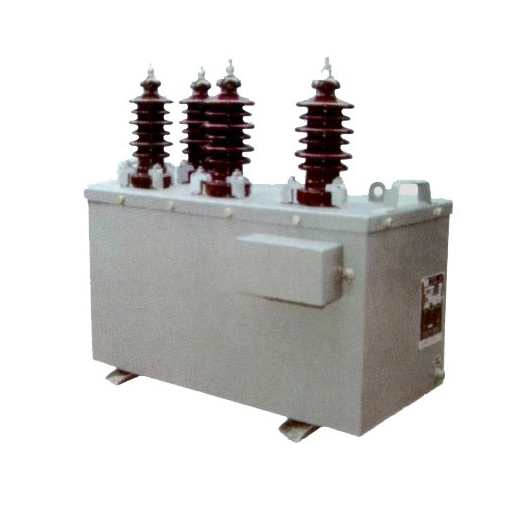
Outdoor 11kV Cast-Resin Voltage Transformer SZW-10K – IEC 61869-3 Compliant
Introduction to the SZW-10K Voltage Transformer
The SZW-10K is a single-phase, outdoor-rated, cast-resin insulated voltage transformer (VT) designed for precise voltage measurement and dependable protective relay operation in 11 kV (IEC nominal) or 10 kV (domestic system equivalent) medium-voltage distribution networks. As a critical component in secondary instrumentation circuits, it provides galvanically isolated, scaled-down replicas of primary system voltages for metering, monitoring, and protection functions. Its robust construction leverages vacuum pressure impregnation (VPI) epoxy resin technology to encapsulate high-grade grain-oriented electrical steel (GOES) cores and copper windings, ensuring long-term dielectric integrity even under harsh environmental conditions.
Operating Principle of Cast-Resin Insulation
Cast-resin insulation in the SZW-10K employs a two-stage VPI process where pre-wound primary and secondary coils are placed in a mold, evacuated to remove air, and then impregnated under pressure with cycloaliphatic epoxy resin. This resin system offers superior tracking resistance (CTI > 600 V), low partial discharge levels (< 5 pC at 1.2 Ur), and excellent thermal stability up to 130°C (Class B insulation). Unlike oil-filled designs, the solid dielectric eliminates fire hazards, prevents leakage, and resists moisture ingress—critical for outdoor installations exposed to rain, dust, and UV radiation. The homogeneous resin matrix also dampens mechanical vibrations from electromagnetic forces, enhancing long-term reliability and reducing audible noise during operation.
Advantages Over Oil-Immersed Designs
Compared to traditional oil-immersed VTs, the SZW-10K’s cast-resin construction provides significant operational and safety benefits. It requires no maintenance-intensive oil sampling or level checks, eliminating risks of environmental contamination from leaks. The absence of flammable oil makes it suitable for urban substations, indoor switchgear rooms, and locations with strict fire codes. Additionally, its compact footprint—typically 30% smaller than equivalent oil units—facilitates easier integration into space-constrained pad-mounted or pole-top configurations. Thermal performance is enhanced through direct heat conduction from windings to the outer resin shell, enabling higher short-time overload capacity (up to 2× rated voltage for 30 seconds) without degradation.
Typical Applications Overview
The SZW-10K is engineered for deployment across diverse medium-voltage infrastructure. Primary use cases include utility-owned outdoor substations (11/0.4 kV or 11/11 kV configurations), industrial plant distribution systems requiring accurate billing metering, and renewable energy interconnection points (e.g., solar farms feeding into 11 kV feeders). Its IEC 61869-3 compliance ensures compatibility with modern digital relays, revenue-class meters, and SCADA systems. The transformer supports both single-secondary (for metering only) and dual-secondary (metering + protection) configurations, with standard ratios such as 11,000/√3 V : 100/√3 V and 11,000/√3 V : 100/3 V for grounded and ungrounded systems respectively.
Technical Specifications
The SZW-10K adheres to stringent electrical and mechanical parameters defined by IEC 61869-3 and GB/T 20840.3, ensuring interoperability and performance consistency across global markets.
| Parameter | Value |
|---|---|
| Primary Voltage (Ur) | 11 kV (IEC); 10 kV (domestic system) |
| Secondary Voltage(s) | 100/√3 V, 100/3 V, or 110/√3 V (configurable) |
| Voltage Ratio | 11,000/√3 : 100/√3 (standard); custom ratios available |
| Accuracy Class | 0.2 / 3P (dual secondary); 0.5 (single secondary) |
| Rated Output (per secondary) | 30 VA (0.2 class), 50 VA (3P class) |
| Insulation Level (Um / Up) | 12 kV / 75 kV (1 min power frequency), 95 kV (lightning impulse) |
| Short-Time Withstand Voltage | 2× Ur for 30 s (thermal), 3× Ur for 1 s (dynamic) |
| Frequency | 50 Hz or 60 Hz ±0.5 Hz |
| Core Material | Grain-Oriented Electrical Steel (GOES), 0.27 mm thickness |
| Insulation System | Cycloaliphatic epoxy resin, VPI process, Class B (130°C) |
| IP Rating | IP54 (terminal box), IP2X (live parts) |
| Ambient Temperature Range | –40°C to +45°C |
| Maximum Altitude | 1,000 m above sea level (derating required above) |
| Relative Humidity | Up to 95% non-condensing |
| Weight | Approx. 45 kg |
Standard Service Conditions
The SZW-10K is rated for continuous operation under IEC 60060-1 standard atmospheric conditions: ambient temperature between –40°C and +45°C, relative humidity ≤95% (non-condensing), and installation altitude not exceeding 1,000 m. At altitudes above 1,000 m, the external insulation withstand voltage must be corrected per IEC 60071-2 using a factor of 1.1 at 2,000 m and 1.25 at 3,000 m. The transformer is designed for vertical mounting on support structures with adequate clearance (≥250 mm) from adjacent equipment to ensure natural convection cooling. Solar radiation exposure is accounted for in thermal design, with surface temperature rise limited to 60 K above ambient under full load.
Electrical Performance Tolerances
Voltage error and phase displacement are tightly controlled per IEC 61869-3. For the 0.2 accuracy class secondary, voltage error must not exceed ±0.2% and phase displacement ≤±10 minutes at 25–100% of rated voltage and 25–100% of rated burden. The 3P protection class allows ±3% voltage error and ±120 minutes phase displacement under fault conditions (up to 190% of Ur). Burden tolerance is ±10% of rated VA; exceeding this may degrade accuracy or cause overheating. The open-circuit secondary voltage must remain within ±0.5% of nominal under no-load conditions, verified during factory testing.
Typical Applications
The SZW-10K serves as a foundational element in modern medium-voltage instrumentation architecture, supporting both legacy and smart-grid deployments.
Substation Secondary Metering
In utility-owned 11 kV/0.4 kV distribution substations, the SZW-10K provides isolated, scaled voltage signals to revenue-class kWh meters (e.g., IEC 62053-22 Class 0.5S). Its 0.2 accuracy class ensures billing precision even under light-load conditions (as low as 1% of rated current when paired with a matching CT). The dual-secondary variant enables simultaneous connection to a metering circuit (0.2 class) and a protection relay (3P class), eliminating the need for separate transformers. Installation typically involves mounting on the HV busbar with bolted terminals rated for 630 A continuous current.
Industrial Power Distribution Systems
Large manufacturing facilities often operate internal 10/11 kV networks fed from dedicated grid connections. Here, the SZW-10K supports power quality monitoring (voltage sag/swell detection), energy management systems, and motor protection schemes. Its robust cast-resin housing withstands industrial pollutants like chemical vapors and conductive dust, which could compromise oil-filled units. In arc-furnace or welding plant environments, the low partial discharge characteristic (<5 pC) prevents premature insulation aging caused by harmonic distortion. The transformer’s thermal resilience allows sustained operation at 110% of rated voltage during grid overvoltage events common in industrial zones.
Renewable Energy Integration
Solar photovoltaic (PV) and wind farms frequently interconnect to 11 kV rural feeders. The SZW-10K enables accurate feed-in tariff metering and anti-islanding protection by supplying synchronized voltage references to inverters and relays. Its fast response time (<20 ms to 90% of final value during step changes) ensures timely detection of islanding conditions per IEEE 1547 or IEC 61727 standards. The outdoor rating eliminates the need for climate-controlled enclosures at remote generation sites, reducing balance-of-system costs. Dual-ratio models can accommodate both local control (100/√3 V) and SCADA telemetry (110/√3 V) requirements.
Rural and Suburban Distribution Networks
In cost-sensitive rural electrification projects, the SZW-10K’s maintenance-free design reduces lifecycle costs compared to oil-filled alternatives. Pole-top installations benefit from its lightweight construction (45 kg) and integrated mounting brackets. The IP54-rated terminal box protects secondary wiring from rain and insect ingress, critical in tropical climates. For ungrounded delta systems common in older networks, the 100/3 V secondary configuration provides residual voltage for ground-fault detection. Field experience shows >99.5% availability over 10 years in Southeast Asian and African deployments with minimal intervention.
Compliance with International Standards
The SZW-10K is certified to IEC 61869-3:2011 (Instrument transformers – Part 3: Electromagnetic voltage transformers) and aligns with Chinese national standard GB/T 20840.3-2013, ensuring global acceptance.
IEC 61869-3 Compliance Details
IEC 61869-3 defines performance, testing, and marking requirements for electromagnetic VTs. The SZW-10K meets all mandatory clauses, including:
– Accuracy verification under defined burdens (Annex B)
– Temperature rise limits (≤60 K for windings)
– Partial discharge levels (<10 pC at 1.2 Ur/√3)
- Short-circuit withstand capability (Clause 12)
- Marking requirements (rated voltage, ratio, accuracy class, serial number)
Factory tests include power frequency withstand (75 kV for 1 min), lightning impulse (95 kV, 1.2/50 µs waveform), and accuracy validation across 20–120% of Ur. Type tests—conducted every 5 years or after design changes—include thermal stability, dynamic short-circuit, and climatic tests per IEC 60068.
GB/T 20840.3 Alignment and Regional Adaptations
While GB/T 20840.3 closely mirrors IEC 61869-3, key differences exist in service conditions and testing emphasis. The Chinese standard specifies a maximum ambient temperature of +40°C (vs. +45°C in IEC) and mandates additional salt fog testing for coastal regions. Domestic 10 kV systems (vs. IEC 11 kV) require adjusted insulation coordination: Um = 12 kV remains identical, but continuous operating voltage is 10/√3 kV instead of 11/√3 kV. The SZW-10K accommodates both by designating primary terminals for 10 kV or 11 kV operation via labeling—no internal modification needed. Certification by CQC (China Quality Certification Centre) validates compliance for mainland China deployments.
Testing and Certification Requirements
Third-party certification by accredited labs (e.g., KEMA, CESI, or SGS) is required for IEC 61869-3 compliance. Tests include:
– Routine tests (100% production): turns ratio, polarity, insulation resistance (>1,000 MΩ at 2,500 V DC), power frequency withstand
– Sample tests (per batch): partial discharge, accuracy, temperature rise
– Type tests (design validation): short-circuit, thermal, seismic (if requested)
Each unit ships with a test report listing individual results. The CE mark indicates conformity with EU Low Voltage Directive 2014/35/EU, referencing EN 61869-3 as the harmonized standard.
On-Site Testing Procedures
Post-installation verification ensures the SZW-10K performs within specifications before energization.
Insulation Resistance Test
Measure insulation resistance between primary winding and ground, and between primary and secondary windings, using a 2,500 V DC megohmmeter. Acceptance criterion: ≥1,000 MΩ at 20°C. Correct for temperature using RT2 = RT1 × 2(T1–T2)/10. Values below 500 MΩ indicate moisture ingress or resin cracking and require investigation. Perform before and after power frequency withstand tests to detect insulation degradation.
Turns Ratio Test
Apply a low-voltage AC source (50–200 V) to the primary and measure secondary voltage with a calibrated voltmeter. Calculate actual ratio and compare to nameplate. Tolerance: ±0.2% for 0.2 class, ±0.5% for 3P class. Use a dedicated turns ratio tester (e.g., Omicron TTR300) for automated comparison. Deviations >1% suggest winding shorts or incorrect tap selection.
Polarity Test
Verify reducing polarity per IEC 61869-3 Figure 3. Connect a 6–12 V battery momentarily between primary terminals H1 (+) and H2 (–). Observe secondary voltage on X1–X2 with a DC voltmeter: a positive kick confirms correct polarity. Incorrect polarity causes 180° phase reversal, leading to metering errors or relay misoperation. Document results in commissioning reports.
Power Frequency Withstand Voltage Test
Apply 75 kV RMS at 50 Hz between primary and ground/secondary for 1 minute. Use a calibrated test transformer with overcurrent protection set to 150% of expected capacitive current (~5 mA). No flashover or disruptive discharge is permitted. Reduce voltage gradually post-test to avoid transient overvoltages. This test validates insulation integrity after transport and installation stresses.
Open-Circuit Characteristic Test
With secondary open, apply 10–120% of rated primary voltage in 10% increments. Record secondary voltage and excitation current. Plot Vsec vs. Vpri; linearity should hold within ±0.3%. Excessive excitation current (>5% of rated secondary current at 120% Ur) indicates core saturation or turn-to-turn faults. This test is critical for VTs used in ferroresonance-prone networks.
Preventive Maintenance Guide
Although cast-resin VTs are largely maintenance-free, periodic checks extend service life beyond 25 years.
Annual Visual and Electrical Inspection
Inspect annually for:
– Cracks, discoloration, or tracking on resin surface
– Loose terminal connections (torque to 25 N·m)
– Corrosion on grounding lugs
– Moisture in terminal box (check desiccant if present)
Perform insulation resistance and turns ratio tests annually in critical applications (e.g., revenue metering). Clean housing with mild detergent; avoid solvents that degrade epoxy. Document findings in asset management systems.
Five-Year Comprehensive Maintenance
Every 5 years, conduct:
– Partial discharge measurement (should remain <10 pC at 1.2 Ur/√3)
- Accuracy re-verification under simulated burden
- Thermal imaging under load to detect hot spots (>10 K above ambient warrants investigation)
– Bolted connection torque verification
Replace terminal box gaskets if hardened or cracked. If PD exceeds 20 pC, consider replacement as internal voids may propagate.
Maintenance Intervals and Fault Diagnosis
| Interval | Action | Fault Indicator |
|---|---|---|
| Annually | Visual inspection, IR test | IR < 500 MΩ → moisture/resin defect |
| Biennially | Ratio & polarity check | Ratio error >0.5% → winding fault |
| 5 Years | PD test, thermal scan | PD >15 pC → internal discharge |
| After Fault | Full suite of tests | Any deviation → replace unit |
Common failure modes include terminal corrosion (due to poor sealing), external flashover (from pollution), and core lamination damage (from mechanical shock during transport). Internal failures are rare but irreversible due to monolithic resin construction.
Conclusion
The SZW-10K 11kV cast-resin voltage transformer represents a mature, field-proven solution for accurate voltage transformation in outdoor medium-voltage applications. Its compliance with IEC 61869-3 and GB/T 20840.3 ensures global interoperability, while the VPI epoxy resin insulation system delivers exceptional dielectric strength, environmental resilience, and fire safety. Key technical advantages include low partial discharge levels (<5 pC), tight accuracy tolerances (±0.2% for metering class), and dual-secondary flexibility for combined metering and protection circuits. Designed for service conditions ranging from arctic cold (–40°C) to tropical humidity (95% RH), it eliminates the operational liabilities of oil-filled alternatives—no leaks, no fire risk, and minimal maintenance. With a design life exceeding 25–30 years under standard loading, the SZW-10K offers a compelling total cost of ownership for utilities, industrial operators, and renewable energy developers deploying reliable, future-ready distribution infrastructure. Its robust performance in real-world scenarios—from urban substations to remote solar farms—validates its role as a cornerstone of modern medium-voltage instrumentation systems.