Article Content
11kV Cast-Resin Voltage Transformer SZW-35 for Metering and Protection – IEC 61869-3 Standard
Introduction to the SZW-35 Voltage Transformer
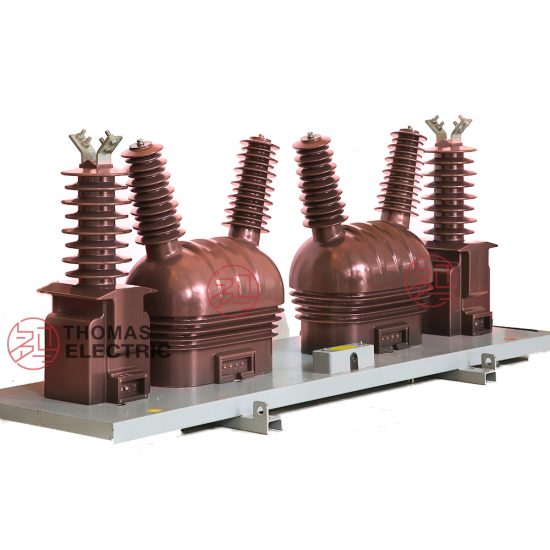
The SZW-35 is a single-phase, indoor/outdoor-rated cast-resin voltage transformer (VT) engineered for high-accuracy voltage measurement and reliable protective relay interfacing in 11kV (IEC) or 10kV (domestic Chinese) medium-voltage distribution systems. Designed per IEC 61869-3 and GB/T 20840.3, it employs vacuum pressure impregnation (VPI) epoxy resin technology to encapsulate its magnetic core and windings, ensuring long-term dielectric integrity, mechanical robustness, and environmental resilience.
Operating Principle of Cast-Resin Insulation
Cast-resin insulation in the SZW-35 utilizes a two-component cycloaliphatic epoxy system cured under vacuum and pressure. This process eliminates air voids and moisture ingress pathways, resulting in a homogeneous solid dielectric with a relative permittivity (εr) of approximately 3.8–4.2 and volume resistivity exceeding 1×10¹⁴ Ω·cm at 20°C. The primary winding—typically rated at 11/√3 kV for phase-to-ground connection—is fully embedded within the resin matrix alongside the secondary winding(s). This monolithic structure provides superior partial discharge performance (<5 pC at 1.2 × Um/√3), critical for maintaining accuracy over decades of service. Unlike oil-filled units, the absence of liquid dielectric eliminates fire hazards, leakage risks, and maintenance-intensive oil sampling.
Advantages Over Oil-Immersed Designs
Compared to traditional oil-immersed VTs, the SZW-35’s cast-resin construction offers significant operational advantages. It is inherently non-flammable (meeting IEC 60695 glow-wire ignition test requirements), requires no periodic oil testing or topping-up, and exhibits negligible aging under thermal cycling between –40°C and +40°C ambient conditions. Its compact footprint (typical height: 650 mm, base diameter: 280 mm) facilitates installation in space-constrained ring main units (RMUs) or pad-mounted substations. Additionally, the epoxy resin provides excellent resistance to tracking and erosion in polluted environments (up to pollution severity class III per IEC 60815), making it suitable for coastal or industrial zones without supplementary creepage extensions.
Typical Applications Overview
The SZW-35 is deployed across utility and industrial networks where precise voltage transformation is essential for revenue metering, fault detection, and power quality monitoring. Common configurations include single-pole mounting on 11kV busbars for phase-to-ground measurement (e.g., 11/√3 kV / 100/√3 V) or line-to-line applications (11 kV / 100 V). Its dual secondary windings—one dedicated to 0.2 or 0.5 class metering, the other to 3P or 6P class protection—enable simultaneous compliance with metrological and safety requirements. Typical installations span urban distribution substations, solar PV collector stations, mining operations, and railway traction feeders operating at nominal 10kV (system maximum voltage Um = 12 kV).
Technical Specifications
The SZW-35 adheres to stringent electrical and environmental parameters defined by international and national standards. Below is a comprehensive specification table followed by detailed contextual explanations.
| Parameter | Value |
|---|---|
| Primary Voltage (Up) | 11/√3 kV (phase-to-ground), 11 kV (line-to-line) |
| Secondary Voltage (Us) | 100/√3 V or 100 V (standard); optional 110/√3 V |
| Voltage Ratio | 11000/√3 : 100/√3 V (i.e., 110:1) |
| Accuracy Class (Metering) | 0.2 or 0.5 per IEC 61869-3 |
| Accuracy Class (Protection) | 3P or 6P per IEC 61869-3 |
| Rated Output (per winding) | 30 VA (0.2 class), 50 VA (0.5 class), 100 VA (3P/6P) |
| Insulation Level (LI/AC) | 95 kV lightning impulse / 42 kV 1-min power frequency |
| Short-Time Thermal Withstand | 1 s at 100 A (primary equivalent) |
| Core Material | Grain-oriented electrical steel (GOES), M4 grade, 0.27 mm lamination |
| Ambient Temperature Range | –40°C to +40°C |
| Altitude Limit | ≤ 1000 m above sea level (derating required >1000 m) |
| Relative Humidity | ≤ 95% non-condensing |
Electrical Performance Parameters
The SZW-35 achieves its specified accuracy through tight control of excitation characteristics and burden matching. For a 0.2-class metering winding, the composite error must not exceed ±0.2% at 80–120% of rated voltage and 25–100% of rated burden. Phase displacement is limited to ±10 minutes under the same conditions. The protection winding (3P class) maintains ratio error within ±3% and phase error within ±120 minutes from 5% to 100% of rated voltage. Core losses are minimized via GOES laminations annealed in hydrogen atmosphere, yielding specific core loss ≤1.1 W/kg at 1.7 T and 50 Hz. The rated thermal burden capacity ensures stable operation even under continuous 120% overvoltage conditions during grid disturbances.
Environmental and Mechanical Ratings
Designed for both indoor switchgear and outdoor pole-top mounting, the SZW-35 features a UV-stabilized resin housing with IP54 ingress protection when mounted vertically. The creepage distance exceeds 25 mm/kV (phase-to-ground), satisfying IEC 60815 requirements for moderate pollution (class II). At altitudes above 1000 m, the power frequency withstand voltage must be reduced by 1% per 100 m increment; e.g., at 2000 m, the AC test voltage becomes 37.8 kV. The unit withstands seismic loads up to 0.3g horizontal acceleration (IEC 60068-2-57), validated through finite element analysis of resin-core bonding integrity. Terminal studs are M12 stainless steel with torque specification of 25 N·m to prevent thermal runaway at connection points.
Typical Applications
The SZW-35’s dual-winding architecture and robust insulation make it adaptable to diverse medium-voltage scenarios requiring simultaneous metering fidelity and protection reliability.
Substation Secondary Metering Systems
In 11kV/0.4kV distribution substations, the SZW-35 supplies standardized 100/√3 V signals to three-phase kWh meters for billing-grade energy measurement. Its 0.2-class accuracy ensures compliance with regulatory frameworks such as China’s DL/T 448 technical management code for electric energy metering devices. The VT is typically connected in wye configuration on the 11kV side, with neutrals grounded through a 100 Ω resistor to limit ferroresonance risk. Burden calculations must account for meter input impedance (typically 10–20 kΩ per phase) plus lead wire resistance; total loop impedance should not exceed 0.5 Ω to maintain class accuracy.
Industrial Power Distribution Networks
Heavy industries—such as steel mills, chemical plants, and data centers—deploy the SZW-35 to feed protective relays (e.g., overvoltage, undervoltage, directional earth fault) while simultaneously powering revenue meters. In arc furnace facilities with severe harmonic distortion (THDV up to 8%), the GOES core’s low hysteresis loss prevents overheating. The 3P-class protection winding delivers linear response down to 5% of rated voltage, enabling sensitive ground-fault detection in high-resistance grounded systems. Installation best practices include shielding secondary cables from motor drive EMI and verifying burden compatibility with relay input specifications (e.g., SEL-351S requires ≤30 VA at 100 V).
Renewable Energy Integration Points
Solar and wind farms utilize the SZW-35 at the point of interconnection (POI) to monitor grid voltage for anti-islanding protection and reactive power control. During cloud transients or wind gusts, rapid voltage fluctuations (±15% in <100 ms) must be accurately captured without saturation. The SZW-35’s knee-point voltage exceeds 180% of rated secondary voltage, ensuring linear operation during LVRT (Low Voltage Ride-Through) events per GB/T 19964. Dual secondaries allow one winding to serve SCADA RTUs (with 0.5-class accuracy) while the other triggers grid-disconnect relays under abnormal voltage conditions. Field tests confirm <0.5° phase shift deviation at 2nd–13th harmonics, critical for synchrophasor applications.
Rural and Suburban Distribution Feeders
In remote areas with long 10kV feeders, the SZW-35 enables voltage regulation via capacitor bank controllers and sectionalizer coordination. Its cast-resin body resists rodent damage and salt fog corrosion—common failure modes for polymer-housed VTs. For single-phase laterals, a single SZW-35 unit provides phase-to-ground voltage for both metering (0.5 class) and overcurrent relay polarization (3P class). Maintenance crews benefit from the unit’s self-diagnostic capability: a sudden rise in excitation current (>10 mA at 100 V secondary) indicates core degradation or turn-to-turn faults. Deployment in unattended pole-top cabinets is facilitated by its –40°C cold-start capability without preheating.
Compliance with International Standards
The SZW-35 is certified to IEC 61869-3:2011 (“Instrument transformers – Part 3: Additional requirements for inductive voltage transformers”) and its Chinese counterpart GB/T 20840.3-2013, ensuring global interoperability and regulatory acceptance.
IEC 61869-3 Certification Requirements
Compliance with IEC 61869-3 mandates rigorous type testing, including temperature rise (≤60 K for resin, measured by resistance method), short-circuit withstand (100 A primary for 1 s without damage), and accuracy verification across burden ranges. The standard defines four accuracy classes for metering (0.1, 0.2, 0.5, 1.0) and two for protection (3P, 6P), each with strict limits on ratio and phase errors. The SZW-35 undergoes factory tests per clause 7.3: power frequency withstand (42 kV for 1 min), partial discharge (<10 pC at 1.2 × 11/√3 kV), and polarity confirmation (reducing polarity standard). Type test reports must be issued by an ISO/IEC 17025-accredited laboratory, with sample retention for five years.
Alignment with GB/T 20840.3
While GB/T 20840.3 mirrors IEC 61869-3 structurally, key differences exist in domestic Chinese practice. GB/T specifies mandatory 10kV primary rating (vs. IEC’s 11kV), though the SZW-35’s design accommodates both via identical insulation coordination (Um = 12 kV). Chinese standards also require additional tests for seismic resilience (GB/T 13540) and radio interference voltage (RIV ≤ 500 μV at 1.1 × Um/√3). Notably, GB/T 20840.3 enforces stricter partial discharge limits (<5 pC) for indoor units—a requirement met by the SZW-35’s VPI process. Certification by CQC (China Quality Certification Centre) is mandatory for grid procurement, involving batch sampling and on-site factory audits.
Harmonization of Global and Domestic Requirements
Duomatech engineers the SZW-35 to satisfy both IEC and GB frameworks without model variants. The core window area (45 cm²) and copper cross-section (primary: 1.5 mm², secondary: 2.5 mm²) are optimized for 50 Hz operation across 10–11 kV systems. Insulation coordination follows IEC 60071, assigning LI/AC = 95/42 kV for Um = 12 kV—identical in both standards. However, labeling differs: IEC units display “11/√3 kV”, while GB-compliant units show “10/√3 kV” on nameplates, despite identical internal construction. This dual-marking strategy simplifies export logistics while meeting local grid codes.
On-Site Testing Procedures
Post-installation verification ensures the SZW-35 performs within specification before energization. All tests follow IEC 60060-1 and IEEE C57.13 protocols.
Insulation Resistance Test
Using a 2500 V DC megohmmeter, measure insulation resistance between primary winding and ground, secondary windings and ground, and inter-winding. Acceptance criteria: ≥1000 MΩ at 20°C. Correct for temperature using RT2 = RT1 × 2(T1–T2)/10. Values below 500 MΩ indicate moisture ingress or resin cracking. Perform before and after power frequency withstand test to detect insulation degradation.
Turns Ratio Verification
Apply 100 V AC to the secondary winding and measure induced primary voltage. Calculate actual ratio = Vp/Vs. Tolerance: ±0.2% for 0.2-class, ±0.5% for 0.5-class, ±3% for 3P-class. Use a calibrated ratio bridge (e.g., Omicron CT Analyzer) for precision. Deviations >1% suggest turn shorts or incorrect tap selection.
Polarity Confirmation
Connect a 6–12 V DC source to primary terminals (H1+, H2–). Momentarily close the circuit while monitoring secondary with a center-zero galvanometer. Deflection must be positive at X1 terminal—confirming reducing polarity per IEC 61869-3 Figure 3. Incorrect polarity causes 180° phase reversal, leading to metering errors or relay misoperation.
Power Frequency Withstand Voltage Test
Apply 42 kV RMS (50 Hz) between primary and grounded secondary/core for 60 seconds. Leakage current must remain <300 mA. Use a test transformer with short-circuit impedance ≤5%. Gradually ramp voltage (2 kV/s) to avoid transient overvoltages. Failure indicates insulation breakdown or surface tracking.
Open-Circuit Characteristic Test
With secondary open, apply 20–120% of rated secondary voltage (20–120 V) to primary and record excitation current. Plot Iexc vs. Vp. Knee-point voltage (where slope increases sharply) must exceed 180 V (180% of 100 V). Excessive excitation current (>15 mA at 100 V) indicates core saturation or interlamination shorts.
Preventive Maintenance Guide
Although cast-resin VTs are largely maintenance-free, periodic checks extend service life beyond 30 years.
Annual Visual and Electrical Inspection
Inspect for resin cracks, tracking marks, or terminal corrosion. Clean surfaces with isopropyl alcohol if contaminated. Verify torque on M12 studs (25 N·m). Measure insulation resistance annually; a 30% drop from baseline warrants further investigation. Check secondary burden with a clamp meter—continuous operation above 120% rated VA accelerates aging. Record ambient temperature during inspection; sustained >45°C may require derating.
Five-Year Comprehensive Assessment
Every 60 months, perform turns ratio, polarity, and open-circuit tests. Compare results to commissioning data; ratio drift >0.3% indicates winding deformation. Conduct thermographic scan under load—hot spots >10 K above ambient suggest poor connections. If installed outdoors, inspect UV degradation of resin (chalking or microcracks) using a 10× magnifier. Replace units showing partial discharge >20 pC during offline testing.
Maintenance Intervals and Fault Diagnosis
| Interval | Action | Fault Indicator |
|---|---|---|
| Annually | Visual check, IR test | IR <500 MΩ → moisture ingress |
| Every 5 years | Ratio, polarity, excitation test | Ratio error >1% → turn shorts |
| After fault event | Full suite + PD measurement | PD >50 pC → insulation damage |
Common failures include secondary winding open-circuit (causing infinite burden and core saturation) and ferroresonance-induced overvoltage (mitigated by damping resistors). Never operate with secondary open—this can generate lethal voltages (>10 kV) due to capacitive coupling.
Conclusion
The SZW-35 11kV cast-resin voltage transformer represents a benchmark in medium-voltage instrumentation, combining IEC 61869-3-certified accuracy with the durability of epoxy-encapsulated construction. Its dual-winding design—featuring 0.2/0.5-class metering and 3P/6P-class protection outputs—enables seamless integration into modern smart grids while meeting stringent revenue metering and safety requirements. The use of GOES silicon steel cores minimizes losses and enhances linearity across harmonic-rich environments, and the VPI resin process ensures decades of maintenance-free operation even in harsh industrial or coastal settings. With a proven service life of 25–30 years under standard loading conditions, the SZW-35 reduces total cost of ownership compared to oil-filled alternatives through elimination of fluid handling, fire mitigation systems, and frequent oil testing. Its compliance with both international (IEC) and domestic (GB) standards provides utilities and industrial operators with a globally deployable solution that maintains metrological integrity under dynamic grid conditions. As distribution networks evolve toward higher penetration of distributed energy resources, the SZW-35’s robust performance during voltage transients and its immunity to environmental stressors position it as a critical enabler of grid reliability and measurement accuracy in the 11kV/10kV domain.