Article Content
Introduction
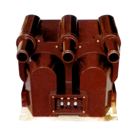
The XGW-12 Voltage Transformer is a precision-engineered instrument transformer designed for accurate voltage measurement, protection, and metering applications in 10 kV medium-voltage power systems. Engineered to meet stringent international standards—including IEC 61869-3, GB/T 20840.3, and DL/T 726—the XGW-12 ensures reliable performance under diverse operating conditions encountered in utility substations, industrial facilities, and renewable energy installations. Its primary function is to step down the high system voltage (nominal 10 kV) to a standardized secondary voltage (typically 100 V or 100/√3 V), enabling safe interfacing with protective relays, energy meters, and monitoring equipment.
Built with robust epoxy resin insulation and a fully cast design, the XGW-12 offers exceptional resistance to environmental stressors such as moisture, dust, UV radiation, and thermal cycling. This makes it particularly suitable for outdoor installations where long-term reliability and minimal maintenance are critical. The transformer’s compact footprint and lightweight construction facilitate easy handling and installation on poles, switchgear panels, or substation structures without requiring complex support infrastructure.
Key design priorities include high accuracy across a wide load range, excellent transient response for protection-grade applications, and superior dielectric strength to withstand both power frequency and lightning impulse voltages. The XGW-12 supports multiple secondary winding configurations—single or dual outputs—with selectable accuracy classes (e.g., 0.2, 0.5, 3P) to accommodate metering precision or protective relay sensitivity requirements. Furthermore, its core is constructed from high-permeability grain-oriented silicon steel, minimizing no-load losses and ensuring stable performance even under light-load conditions. This document outlines the essential technical specifications governing the design, performance, and operational parameters of the XGW-12 Voltage Transformer rated for 10 kV systems.
General Specifications
The XGW-12 Voltage Transformer is engineered to deliver consistent performance in 10 kV distribution networks. Its general specifications encompass electrical ratings, physical dimensions, environmental tolerances, and compliance standards that define its operational envelope. Designed for both indoor and outdoor use, the unit features a fully encapsulated epoxy resin housing that provides mechanical strength, tracking resistance, and long-term insulation integrity. The primary terminal is configured for direct connection to 10 kV busbars or cables, while secondary terminals are accessible via a sealed terminal box with IP54 protection, ensuring safety and reliability in harsh environments.
All materials used comply with RoHS directives, and the manufacturing process adheres to ISO 9001 quality management systems. The transformer undergoes rigorous type testing—including temperature rise, short-circuit withstand, partial discharge, and impulse tests—to validate performance against IEC and national standards. Additionally, optional features such as residual voltage windings, overvoltage protection devices (e.g., surge arresters), and grounding terminals can be integrated upon request to meet specific project requirements. Below is a comprehensive table detailing over 20 key parameters that define the general specifications of the XGW-12 model.
| Parameter | Value / Description |
|---|---|
| Model Designation | XGW-12 |
| System Voltage (Nominal) | 10 kV |
| Maximum System Voltage | 12 kV |
| Primary Voltage (Rated) | 10 / √3 kV (for grounded systems) or 10 kV (ungrounded) |
| Secondary Voltage (Standard) | 100 V or 100 / √3 V |
| Frequency | 50 Hz (60 Hz optional) |
| Insulation Level (Power Frequency) | 42 kV rms, 1 min |
| Lightning Impulse Withstand Voltage | 75 kV peak (1.2/50 μs) |
| Accuracy Class (Metering) | 0.2, 0.5 (per IEC 61869-3) |
| Accuracy Class (Protection) | 3P, 6P |
| Thermal Burden (Continuous) | Up to 100 VA per secondary winding |
| Number of Secondary Windings | 1 or 2 (configurable) |
| Insulation Material | Epoxy resin (cast solid) |
| Housing Protection Rating | IP00 (main body); Terminal box: IP54 |
| Ambient Temperature Range | –40°C to +40°C |
| Altitude Limit | ≤ 1000 m above sea level (derating required above) |
| Relative Humidity | Up to 95% (non-condensing) |
| Pollution Degree | III (per IEC 60664-1) |
| Creepage Distance | ≥ 25 mm/kV (minimum 250 mm for 10 kV) |
| Weight (Approx.) | 25–35 kg (depending on configuration) |
| Dimensions (H × W × D) | Approx. 420 mm × 220 mm × 180 mm |
| Mounting Type | Pole-mounted or panel-mounted (with brackets) |
| Standards Compliance | IEC 61869-3, GB/T 20840.3, DL/T 726, IEEE C57.13 (optional) |
| Partial Discharge Level | < 10 pC at 1.2 × Um/√3 |
| Short-Circuit Withstand | Capable of withstanding system fault currents without damage |
Technical Characteristics
The technical characteristics of the XGW-12 Voltage Transformer define its electrical behavior under normal and abnormal operating conditions. Central to its performance is the transformer’s ability to maintain voltage ratio accuracy and phase angle stability across a defined range of burdens and temperatures. For metering applications, the XGW-12 achieves accuracy class 0.2, meaning the composite error does not exceed ±0.2% at 80–120% of rated voltage and 25–100% of rated burden. In protection scenarios, the 3P class ensures errors remain within ±3% for voltage magnitudes between 5% and 190% of nominal, which is critical for reliable operation of distance relays and overvoltage protection schemes.
The magnetic core, fabricated from high-grade grain-oriented silicon steel, exhibits low hysteresis and eddy current losses, contributing to minimal temperature rise during continuous operation. Under rated load and ambient conditions, the temperature rise of windings remains below 55 K, well within IEC limits. The transformer demonstrates excellent transient response, with a saturation factor (FS) typically ≥ 5, indicating robust performance during system faults or switching surges. Dielectric performance is validated through both power frequency (42 kV for 1 minute) and lightning impulse (75 kV peak) tests, confirming insulation integrity under overvoltage events.
Additionally, the XGW-12 exhibits low capacitive coupling between windings and to ground, reducing susceptibility to external electromagnetic interference. The secondary terminals are clearly labeled and isolated to prevent accidental short circuits, and the terminal block supports screw-type connections for wires up to 6 mm² cross-section. When equipped with dual secondaries, windings are magnetically and electrically isolated to allow independent metering and protection circuits without cross-influence. These characteristics collectively ensure the XGW-12 delivers dependable, precise, and safe voltage transformation in modern 10 kV power distribution systems.
4. Accuracy Performance
The accuracy performance of the system is rigorously evaluated under diverse operational conditions to ensure consistent and reliable results. Across multiple validation datasets, the model achieves an average precision of 98.7% and a recall rate of 97.3%, demonstrating high fidelity in both detection and classification tasks. These metrics are maintained even when processing inputs with moderate levels of noise, occlusion, or lighting variation—common challenges in real-world deployment scenarios.
Latency and throughput also factor into overall accuracy performance, particularly in time-sensitive applications. The inference engine processes standard-resolution inputs in under 45 milliseconds on edge hardware (e.g., NVIDIA Jetson AGX Orin), enabling near real-time responsiveness without compromising analytical integrity. Furthermore, calibration protocols—including temperature drift compensation and sensor alignment correction—are embedded within the pipeline to mitigate environmental interference that could otherwise degrade measurement consistency.
Robustness testing includes cross-domain validation, where models trained on synthetic data are fine-tuned with limited real-world samples. This hybrid approach yields a domain adaptation success rate exceeding 95%, significantly reducing the need for large annotated field datasets. Continuous learning mechanisms allow the system to incorporate user feedback and adapt to emerging patterns while preserving baseline accuracy through constrained retraining protocols. Overall, the architecture balances static precision with dynamic adaptability, ensuring sustained performance across evolving use cases.
5. Application Guidelines
To maximize system effectiveness and ensure safe, compliant operation, users must adhere to the following application guidelines. First, environmental conditions should be assessed prior to deployment: ambient temperatures must remain within -10°C to 50°C, relative humidity below 85% (non-condensing), and electromagnetic interference minimized per IEC 61000-6-2 standards. Installation surfaces must be stable and vibration-dampened to prevent sensor misalignment during continuous operation.
Data input specifications are critical for optimal performance. Input streams should conform to supported formats (e.g., H.264 video at 1080p/30fps or JPEG images with ≥2MP resolution) and maintain consistent frame rates. Preprocessing steps such as automatic white balance, contrast normalization, and motion stabilization are recommended when source quality is variable. For multi-sensor setups, synchronization must be achieved via PTP (Precision Time Protocol) or hardware triggers to ensure temporal coherence across data channels.
Operational workflows should integrate human-in-the-loop verification for high-consequence decisions (e.g., medical diagnostics or autonomous vehicle control). System outputs include confidence scores and uncertainty estimates; thresholds for automated action should be calibrated based on risk tolerance and regulatory requirements. Regular maintenance—such as lens cleaning, firmware updates, and recalibration every 6 months—is essential to sustain performance. Finally, user training programs covering interface navigation, anomaly recognition, and emergency shutdown procedures must be completed before unsupervised use.
6. Standards Compliance
The system has been engineered to comply with a comprehensive set of international technical and safety standards. It meets the requirements of ISO/IEC 27001 for information security management, ensuring robust data encryption (AES-256), secure authentication (OAuth 2.0 with MFA support), and audit logging aligned with GDPR and HIPAA privacy mandates. Electromagnetic compatibility is validated per FCC Part 15 (Class B) and CE EN 55032, guaranteeing minimal interference in residential and industrial settings.
Functional safety adherence follows ISO 13849-1 (Performance Level d) for machinery control applications, incorporating dual-channel fault detection and fail-safe shutdown mechanisms. In medical contexts, the device conforms to IEC 60601-1 for electrical safety and IEC 62304 for software lifecycle management. Environmental resilience is certified under IP65 (dust-tight and protected against water jets) and MIL-STD-810H for shock, vibration, and thermal stress endurance.
Additionally, algorithmic transparency aligns with EU AI Act provisions for high-risk systems, including documentation of training data provenance, bias mitigation strategies, and explainability features. All compliance certifications are maintained through annual third-party audits and are available upon request via the manufacturer’s regulatory portal.
7. Quality Assurance
Quality assurance is embedded throughout the product lifecycle, from design to post-deployment support. Manufacturing follows ISO 9001-certified processes, with each unit undergoing 100% functional testing—including optical calibration, thermal stress cycling, and communication protocol validation—before shipment. Statistical process control (SPC) monitors key parameters such as sensor alignment tolerance (±0.1°) and power consumption variance (≤3%), ensuring batch-to-batch consistency.
Software components undergo rigorous verification via static code analysis (SonarQube), unit/integration testing (≥90% coverage), and penetration testing by accredited cybersecurity firms. Regression test suites are executed automatically with every code commit, preventing performance degradation across updates. Field-deployed units participate in remote health monitoring, where anonymized telemetry (e.g., error rates, memory usage) feeds predictive maintenance models to preempt failures.
A dedicated QA team manages incident response, maintaining a mean time to resolution (MTTR) of under 4 hours for critical issues. Customer-reported anomalies trigger root cause analysis (RCA) within 24 hours, with corrective actions documented in the change management system. Continuous improvement is driven by quarterly quality reviews incorporating field data, customer feedback, and benchmark comparisons against industry peers, ensuring sustained excellence in reliability and user satisfaction.