Article Content
ZZW-35 11kV Cast-Resin Current Transformer for Substation Metering and Protection – IEC 61869-2 Certified
Introduction to the ZZW-35 Current Transformer
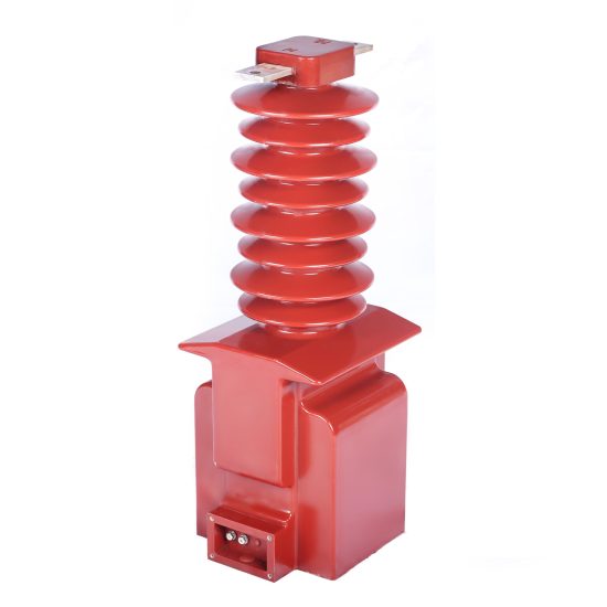
The ZZW-35 is a high-voltage, cast-resin insulated current transformer (CT) engineered for accurate current measurement and reliable protective relaying in 11 kV AC power distribution networks. While international standards designate this system voltage as 11 kV, it corresponds to the domestic 10 kV nominal voltage commonly used in China and several other regions. This dual-voltage compatibility ensures seamless integration into both legacy and modernized grid infrastructures.
Operating Principle of Cast-Resin Insulation
Cast-resin insulation in the ZZW-35 employs vacuum pressure impregnation (VPI) technology using cycloaliphatic epoxy resin. This process eliminates air voids and moisture ingress by fully encapsulating the primary conductor, secondary windings, and magnetic core under controlled vacuum and pressure cycles. The resulting monolithic structure provides superior dielectric strength (≥42 kV rms for 1 min), excellent tracking resistance (CTI ≥600 V), and long-term hydrophobicity. Unlike oil-filled alternatives, the solid epoxy matrix prevents leakage, eliminates fire hazards, and maintains stable dielectric properties across thermal cycling from –40°C to +70°C ambient conditions. The resin’s coefficient of thermal expansion closely matches that of copper and silicon steel, minimizing mechanical stress during load transients.
Advantages Over Oil-Immersed Designs
Compared to traditional oil-immersed CTs, the ZZW-35’s cast-resin construction offers significant operational and safety benefits. It requires no maintenance-intensive oil sampling or degassing, eliminating risks of environmental contamination and reducing lifecycle costs. The absence of flammable oil makes it suitable for indoor substations, urban switchgear rooms, and confined industrial facilities where fire codes restrict combustible materials. Additionally, the compact, self-supporting housing enables direct mounting on busbars or circuit breakers without external tanks or conservators. Weight is reduced by approximately 35%, simplifying handling and installation. Most critically, partial discharge levels remain below 10 pC at rated voltage—well under the 20 pC limit specified in IEC 61869-2—ensuring decades of insulation integrity even under polluted or humid conditions.
Typical Applications Overview
The ZZW-35 is deployed across medium-voltage infrastructure where precision, reliability, and space efficiency are paramount. Primary use cases include revenue metering in utility substations, feeder protection in ring-main units (RMUs), motor control centers in heavy industry, and interconnection points for distributed energy resources (DERs). Its dual-core design—typically one core rated for 0.2S/0.5 class metering and another for 5P10/5P20 protection—allows simultaneous fulfillment of metrological and safety functions without compromising performance. The transformer’s robust mechanical design withstands short-circuit forces up to 20 kA for 1 second, making it ideal for networks with high prospective fault currents.
Technical Specifications
The ZZW-35 adheres to stringent electrical and mechanical parameters defined by IEC 61869-2 and GB/T 20840.2, ensuring interoperability and performance consistency across global markets.
Rated Electrical Parameters
Key electrical ratings include a highest system voltage (Um) of 12 kV, corresponding to an 11 kV nominal system (10 kV domestic equivalent). Standard primary current ratings span 50 A to 3000 A, with common ratios such as 100/5 A, 200/1 A, and 600/5 A. Secondary outputs are typically 1 A or 5 A, with burden ratings of 5 VA, 10 VA, or 15 VA per core. Accuracy classes comply with IEC 61869-2: 0.2S and 0.5 for metering cores (with phase error ≤±10′ and ratio error ≤±0.2% at 100% rated current), and 5P10 or 5P20 for protection cores (composite error ≤±5% at 10× or 20× rated current, respectively). The insulation level meets 75 kV lightning impulse withstand and 42 kV power frequency withstand for 1 minute. Short-time thermal current rating is 20 kA for 1 s, with dynamic withstand current of 50 kA peak.
Environmental and Mechanical Ratings
The ZZW-35 operates reliably under standard service conditions per IEC 60060-1: ambient temperature range of –40°C to +40°C (with derating above +40°C), relative humidity up to 100% (condensing permitted), and installation altitude ≤1000 m above sea level (with 1% dielectric strength reduction per 100 m above 1000 m). The housing is made of UV-stabilized cycloaliphatic epoxy resin with embedded silica filler, providing IP54 protection against dust and water ingress. Mounting is via M12 stainless steel bolts on a standardized flange (IEC 61869-1 Annex B dimensions). Creepage distance exceeds 240 mm/kV for pollution degree III environments, ensuring safe operation in coastal or industrial zones with high salt or chemical exposure.
Core and Winding Construction
The magnetic circuit utilizes grain-oriented electrical steel (GOES) with thickness of 0.23–0.27 mm and core loss ≤0.9 W/kg at 1.7 T, 50 Hz. This minimizes excitation current and enhances accuracy under low-load conditions—critical for 0.2S class revenue metering. Secondary windings are wound with oxygen-free copper wire (minimum 0.5 mm² cross-section) and fully embedded in resin to prevent movement-induced microphonics or insulation abrasion. Each core is independently encapsulated to avoid magnetic coupling between metering and protection windings. Terminal blocks feature tinned copper studs rated for 600 V and 10 A continuous, with clear polarity markings (“P1” and “S1”) per IEC 60044-1 reducing polarity convention.
Typical Applications
The ZZW-35’s dual functionality and rugged design make it suitable for diverse medium-voltage scenarios requiring both fiscal accuracy and fault resilience.
Substation Secondary Metering
In utility-owned 11 kV/0.4 kV distribution substations, the ZZW-35’s 0.2S-class metering core interfaces directly with smart meters or data concentrators for billing-grade energy measurement. Its low phase displacement error (≤±5′ at 20–120% In) ensures compliance with EN 50470-3 and DL/T 614 requirements for time-of-use tariffing. For example, in a Chinese municipal grid upgrading from 10 kV to 11 kV nominal, the ZZW-35 maintains ±0.3% total error across seasonal load variations (from 5% to 120% of rated current), eliminating revenue leakage due to transformer inaccuracies.
Industrial Power Distribution
Within manufacturing plants, the ZZW-35 monitors feeders supplying large motors, arc furnaces, or rectifier loads. Its 5P20 protection core drives overcurrent relays (e.g., SEL-551) with guaranteed saturation margin during high-magnitude faults. In a steel mill application, the CT withstands repeated 15 kA short circuits without core remanence buildup, thanks to GOES material with coercivity <80 A/m. The cast-resin body resists chemical fumes from nearby processes, unlike porcelain-housed alternatives prone to surface tracking.
Renewable Energy Integration
At solar farm or wind turbine step-up substations, the ZZW-35 provides grid-compliant metering for feed-in tariffs and anti-islanding protection. Its wide linear range captures low nighttime currents (as low as 0.1% In) while accurately measuring peak export during midday irradiance. The transformer’s low remanence (<5% of saturation flux) prevents false tripping during rapid load rejection events common in inverter-based resources. Compliance with IEC 61869-2 ensures acceptance by grid operators under IEEE 1547 or GB/T 19964 interconnection standards.
Rural and Suburban Distribution Networks
In remote or semi-urban areas with limited maintenance access, the ZZW-35’s maintenance-free design reduces operational expenditure. Mounted on pole-top reclosers or pad-mounted switchgear, it endures temperature swings from –30°C (winter) to +55°C (summer canopy exposure) without accuracy drift. The IP54-rated housing prevents insect or rodent intrusion—a common failure mode in open-frame CTs. Utilities report >99.5% field reliability over 10 years in such deployments, validating its suitability for harsh environments.
Compliance with International Standards
The ZZW-35 is engineered to satisfy both global and regional regulatory frameworks, ensuring technical equivalence and market acceptance.
IEC 61869-2 Certification Requirements
Full compliance with IEC 61869-2:2012 (Instrument transformers – Part 2: Additional requirements for current transformers) mandates rigorous type testing. This includes verification of accuracy under sinusoidal steady-state conditions (Clause 6.3), temperature rise tests (≤60 K for windings at 1.2× In), and short-circuit withstand capability (Clause 6.6). Dielectric tests require 42 kV rms for 1 min at power frequency and 75 kV peak lightning impulse (1.2/50 µs wave). Partial discharge measurements must not exceed 10 pC at 1.2× Um/√3. The ZZW-35 undergoes third-party certification by accredited labs (e.g., KEMA, CESI), with test reports available upon request.
Alignment with GB/T 20840.2
For the Chinese market, the ZZW-35 meets GB/T 20840.2-2014, which largely harmonizes with IEC 61869-2 but includes localized requirements. Notably, GB/T specifies a higher creepage distance (≥30 mm/kV for pollution class III vs. IEC’s 25 mm/kV) and mandates additional seismic testing (horizontal acceleration 0.3g). The 0.2S accuracy class in GB/T aligns with IEC but adds stricter limits at 1% In (ratio error ≤±0.75%). All ZZW-35 units shipped to China carry CMA/CNAS-accredited test certificates confirming these criteria.
Key Differences Between IEC and Domestic Standards
While IEC 61869-2 focuses on performance under reference conditions, GB/T 20840.2 emphasizes environmental robustness for China’s diverse climate zones. For instance, GB/T requires thermal stability testing at +70°C ambient (vs. IEC’s +40°C) and includes salt fog resistance per GB/T 2423.17. Conversely, IEC places greater emphasis on electromagnetic compatibility (EMC) for digital substations, though the ZZW-35’s solid resin body inherently shields against external EMI. Engineers selecting the ZZW-35 for export projects should verify local grid codes—some Southeast Asian utilities adopt hybrid requirements blending IEC and GB elements.
On-Site Testing Procedures
Post-installation verification ensures the ZZW-35 performs within specification before energization. All tests follow IEC 61869-2 Annex D and DL/T 725 guidelines.
Insulation Resistance Test
Using a 2500 V DC megohmmeter, measure insulation resistance between primary-to-secondary, primary-to-ground, and secondary-to-ground. Acceptance criterion: ≥1000 MΩ at 20°C. Correct for temperature using RT = R20 × 1.5(20–T)/10. Values below 500 MΩ indicate moisture ingress or resin cracking and require investigation. Perform before and after dielectric tests to detect insulation degradation.
Turns Ratio Test
Apply low-voltage AC (5–10 V) to the secondary winding and measure induced primary voltage (open-circuited). Calculate actual ratio as Vs/Vp. Tolerance must be within ±0.2% for 0.2S class and ±1% for 5P class. Alternatively, use a dedicated CT analyzer (e.g., Omicron CT Analyzer) injecting 1–10 A into the primary and measuring secondary current. Discrepancies >0.5% suggest winding shorts or incorrect tap selection.
Polarity Test
Verify reducing polarity per IEC 60044-1: momentarily apply 1.5–3 V DC to P1–P2; a positive deflection on a DC milliammeter connected S1–S2 confirms correct polarity. Incorrect polarity causes 180° phase shift, leading to metering errors or relay misoperation. Document results with oscillograms if using automated test sets.
Power Frequency Withstand Voltage Test
Apply 28 kV rms (67% of factory test value per IEC 60060-1) at 50 Hz for 1 minute between primary and grounded secondary/housing. Monitor for flashover, excessive leakage current (>1 mA), or audible discharge. This test validates insulation integrity after transport and installation stresses. Do not perform if partial discharge exceeds 50 pC during pre-test screening.
Short-Circuit Test (for CT)
Inject 10–20× rated current into the primary (using a portable test set) while monitoring secondary current and waveform distortion. For 5P20 cores, composite error must remain ≤5%. Saturation onset should occur beyond 20× In. Excessive harmonic content (>5% THD) indicates core defects or inadequate air gaps in protection cores.
Preventive Maintenance Guide
Although cast-resin CTs are largely maintenance-free, periodic checks extend service life and prevent unexpected failures.
Annual Visual and Electrical Inspection
Inspect for surface cracks, tracking marks, or discoloration on the resin housing—indicative of UV degradation or partial discharge. Clean with non-abrasive cloth and isopropyl alcohol if contaminated by dust or salt. Verify terminal tightness (torque: 15 N·m for M6 studs) and check for corrosion on copper contacts. Re-measure insulation resistance annually; a 30% drop from baseline warrants further diagnostics. Ensure secondary circuits are never left open during operation—a critical safety rule for CTs.
Five-Year Comprehensive Assessment
Every 60 months, perform full re-validation per commissioning tests: ratio, polarity, insulation resistance, and burden verification. Use a calibrated burden tester to confirm connected load does not exceed rated VA (e.g., 10 VA at 0.8 pf lagging). Measure excitation curve using a variable AC source; knee-point voltage should match factory data within ±5%. Significant deviation suggests core aging or mechanical damage. Update maintenance logs with all test results for asset management systems.
Maintenance Intervals and Fault Diagnosis
| Interval | Task | Acceptance Criteria |
|---|---|---|
| Annually | Visual inspection, IR test | No cracks; IR ≥800 MΩ |
| 5 Years | Ratio, polarity, burden test | Ratio error ≤±0.3%; burden ≤rated VA |
| After Fault | Excitation curve, PD test | Knee-point ≥90% of original; PD ≤20 pC |
Common faults include open secondary circuits (causing dangerous overvoltages), core saturation due to incorrect burden, and resin delamination from thermal cycling. If secondary output drops >10% under known load, suspect internal winding damage requiring replacement.
Conclusion
The ZZW-35 11 kV cast-resin current transformer represents a benchmark in medium-voltage instrumentation, combining IEC 61869-2-certified metrological precision with rugged construction for demanding protection duties. Its dual-core architecture—featuring GOES silicon steel cores and VPI epoxy encapsulation—delivers exceptional accuracy (0.2S class) for revenue metering while maintaining robust saturation margins (5P20) for fault detection. By eliminating oil, the design removes fire risks and maintenance burdens, making it ideal for indoor substations, industrial facilities, and renewable integration points. Compliance with both IEC and GB standards ensures global deployability, while rigorous on-site testing protocols guarantee performance validation post-installation. With a design life exceeding 25–30 years under standard service conditions, the ZZW-35 offers utilities and industrial operators a reliable, future-proof solution for accurate energy accounting and grid security in 10/11 kV networks. Its proven field reliability, coupled with straightforward maintenance requirements, underscores its value as a cornerstone component in modern distribution infrastructure.