Product Overview
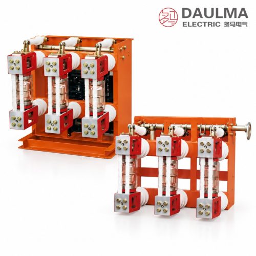
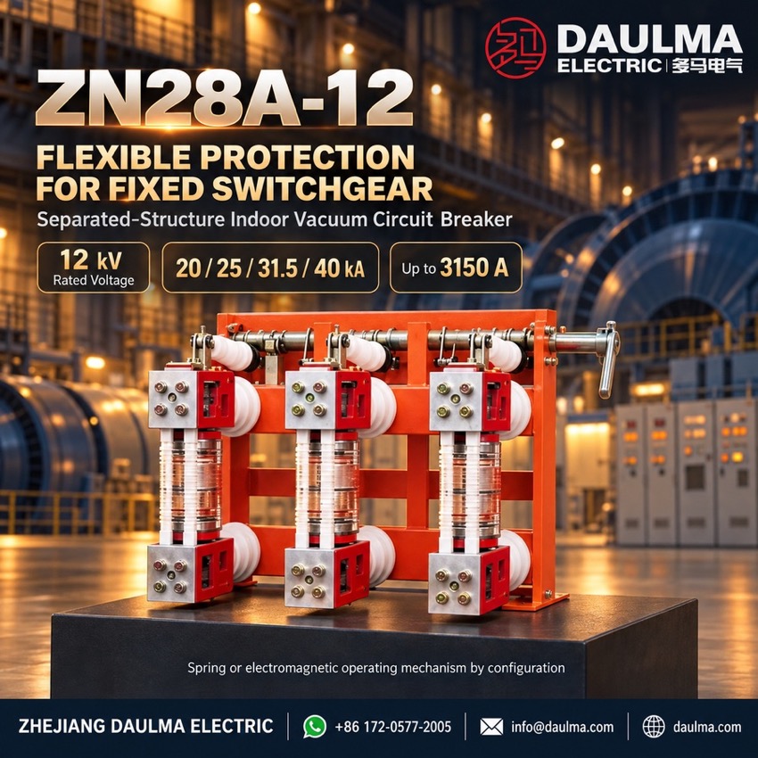
The ZN28-12 is a three-phase AC 50 Hz indoor high-voltage vacuum circuit breaker rated 12 kV for fixed switchgear installations. Rated currents run 630 A to 3150 A with short-circuit breaking capacities of 20 kA to 40 kA, serving distribution and motor feeders in industrial plants, substations and mining networks. Integrated ZN28-12 and separated ZN28A-12 structures suit different cabinet layouts.
Product Display
Model Designation
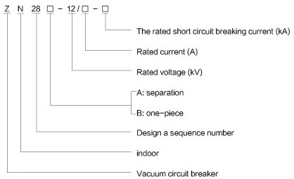
Model format: ZN 28 − 12 □ − □ (A / B structure)
- Z — Vacuum circuit breaker
- N — Indoor installation
- 28 — Design sequence number
- 12 — Rated voltage (kV)
- A — Separated structure; B — One-piece (integrated) structure
- First □ — Rated current (A)
- Second □ — Rated short-circuit breaking current (kA)
Service Conditions
- Ambient temperature: −10 °C to +40 °C
- Altitude: not exceeding 1000 m above sea level
- Relative humidity: daily average ≤ 95%, monthly average ≤ 90%; vapour pressure daily ≤ 2.2 kPa, monthly ≤ 1.8 kPa
- Air quality: free from dust, smoke, corrosive or combustible gases, vapours and salt spray
- Vibration: minimal external vibration or ground motion
- Electromagnetic interference: induced voltage in secondary system ≤ 1.6 kV
Construction
A sealed longitudinal-magnetic-field vacuum interrupter provides arc extinction. The frame carries six rear-mounted insulators: three upper insulators secure the moving bracket and three lower insulators hold the static bracket, with the bracket rear ends forming the primary terminals P1 and P2. The interrupter sits between the brackets and couples to the main shaft through an insulating rod and swing arm, while two further insulating rods tie the brackets into a rigid structure.
Operation is by CT17/CT19 spring-charged or CD17/CD10A electromagnetic mechanism; the main shaft rotates 58° ± 1° through a connecting rod, and the opening spring and oil buffer are enclosed within the frame. Pre-drilled base holes simplify mounting in fixed cabinets.
Technical Data
| Item | Unit | 20kA | 25kA | 31.5kA | 40kA |
|---|---|---|---|---|---|
| Rated Voltage | kV | 12 | |||
| Rated Current | A | 630 1000 1250 |
1250 1600 |
1250 1600 2000 2500 |
1600 2500 3150 |
| Rated Short-Circuit Breaking Current | kA | 20 | 25 | 31.5 | 40 |
| Rated Short-Circuit Closing Current (Peak) | kA | 50 | 63 | 80 | 100 |
| 4s Rated Short-Time Withstand Current | kA | 20 | 25 | 31.5 | 40 |
| Power Frequency Withstand Voltage (closed / after break) | kV | 42 (break 48) | |||
| Impulse Withstand Voltage (closed / after break) | kV | 75 (break 85) | |||
| Rated Operating Sequence | — | O – 0.3 s – C, O – 180 s – C | |||
| Mechanical Life | Operations | 10000 | |||
| Operating Mechanism Rated Voltage | V | 110 / 220 | 110 / 220 | 220 | 220 |
| Contact Opening Distance | mm | 11 ± 1 | |||
| Main Circuit Resistance | μΩ | ≤ 50 | |||
Standards
Designed and type-tested in accordance with GB 1984 and the corresponding IEC requirements for AC high-voltage circuit breakers, including IEC 62271-100 and GB/T 11022.
Installation & Dimensions
Installation Diagram
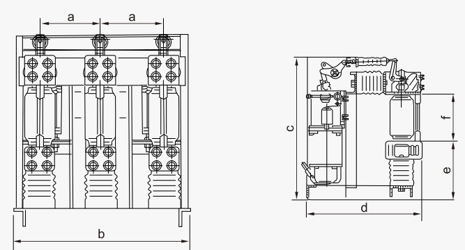
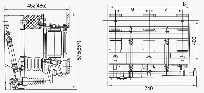
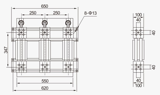
The breaker is bolted to pre-drilled base holes in fixed switchgear cabinets such as GG-1A(Z) or XGN2A-10(Z). Align the primary terminals P1/P2 correctly and keep safe clearances in line with local electrical codes.
| Dimension | Value (mm) |
|---|---|
| a | 230 (20/25/31.5 kA); 275 ± 1 (40 kA) |
| b | 600 (20/25/31.5 kA); 690 (40 kA) |
| c | 707 (20/25/31.5 kA); 842 (40 kA) |
| d | 560 (20/25/31.5 kA); 652 (40 kA) |
| e | 293–20 (20/25/31.5 kA); 342–20 (40 kA) |
| f | 227 ± 1 (all ratings) |