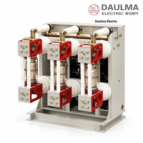
Product Overview
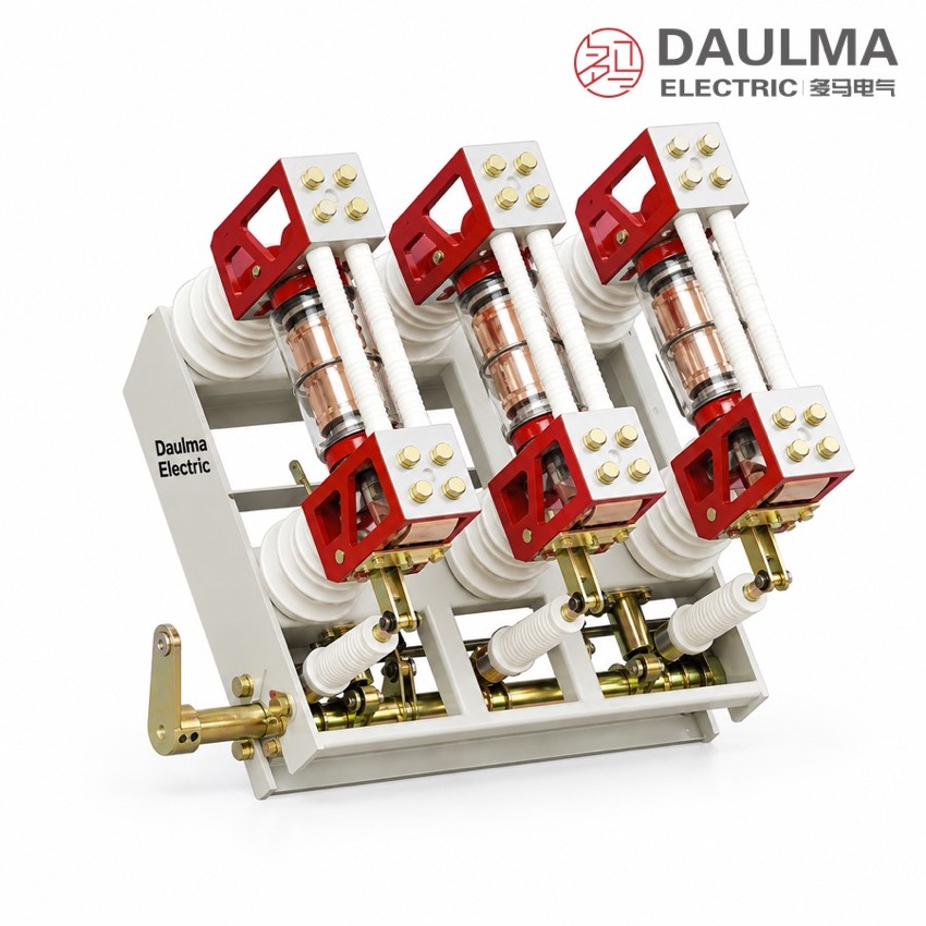
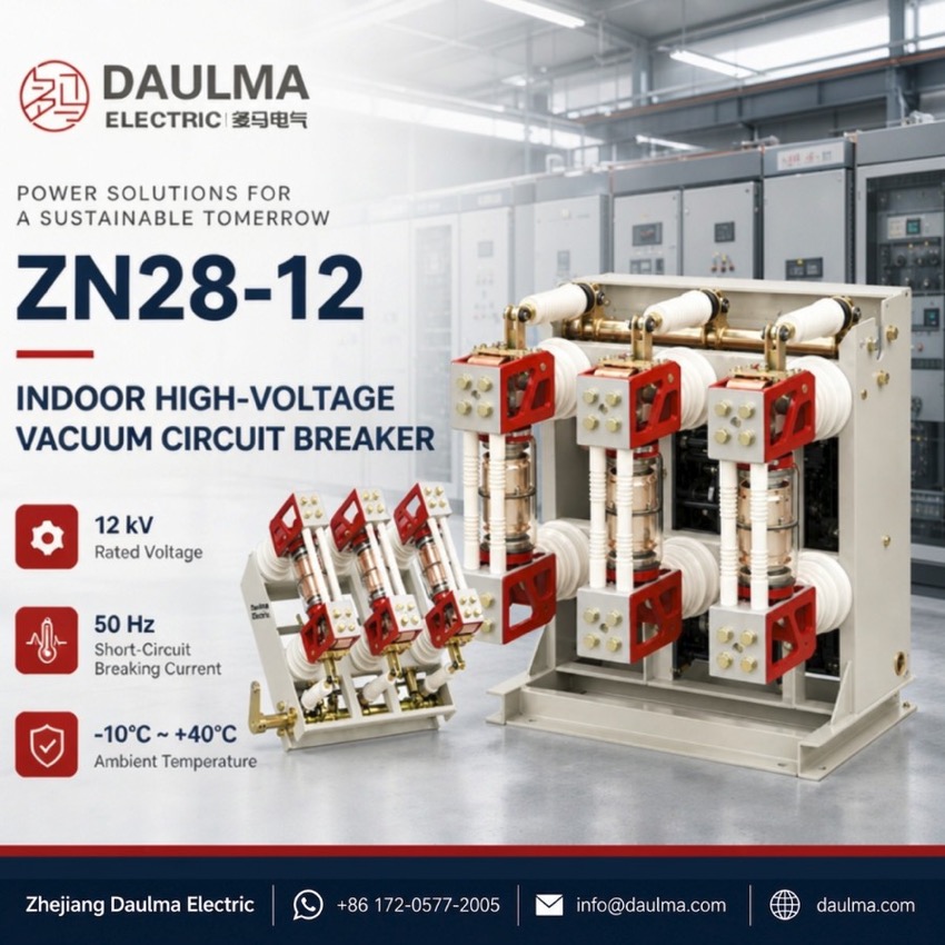
The ZN28G(A)-12 is a three-phase 50 Hz indoor high-voltage vacuum circuit breaker rated 12 kV with side-mounted pole-unit construction, used to control and protect power plants, substations and industrial or mining distribution systems. Rated currents from 630 A to 3150 A combine with breaking capacities of 20 kA, 31.5 kA and 40 kA, and the breaker fits both handcart-type and fixed-type metal-enclosed switchgear for frequent operation.
Product Display
Model Designation
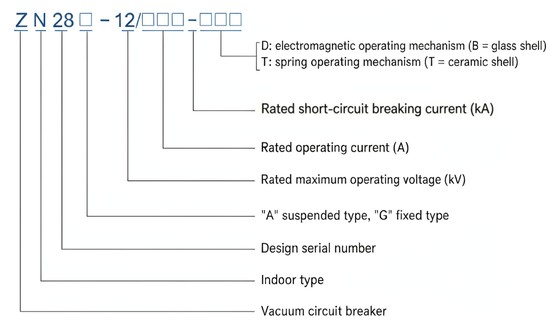
Model format: ZN 28 □ − 12 / □□□ − □□□
- Z — Vacuum circuit breaker
- N — Indoor installation
- 28 — Design sequence number
- □ — Mounting form: G fixed, A suspended
- 12 — Rated voltage (kV)
- First □□□ — Rated current (A)
- Second □□□ — Rated short-circuit breaking current (kA)
- D / T — D electromagnetic mechanism (glass envelope), T spring mechanism (ceramic envelope)
Example: ZN28G-12/1250-31.5 denotes a 12 kV fixed-type side-mounted indoor vacuum circuit breaker with 1250 A rated current and 31.5 kA rated short-circuit breaking current.
Service Conditions
- Ambient temperature: −10 °C to +40 °C (down to −30 °C during storage and transport)
- Altitude: not above 1000 m (higher sites require a correspondingly raised insulation level)
- Seismic intensity: not above degree 8
- Relative humidity: daily average ≤ 95%, monthly average ≤ 90%
- Environment: free from fire, explosion hazard, serious pollution, chemical corrosion and violent vibration
Construction
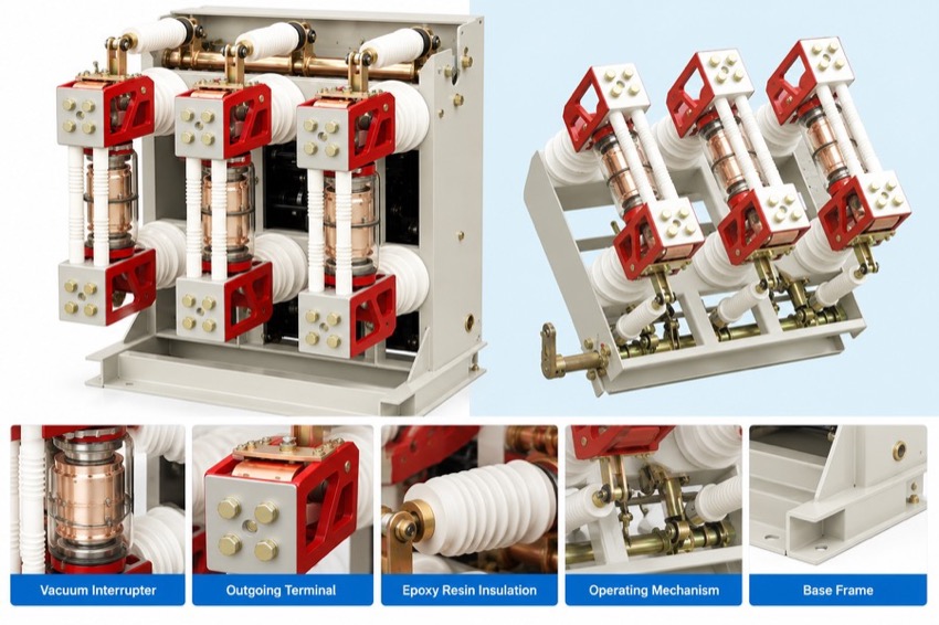
The three vacuum-interrupter pole units are mounted side by side on a common frame, so the same breaker serves handcart-type and fixed-type switchgear; the G fixed type bolts directly into fixed cubicles while the A suspended variant suits handcart mounting. The arc is extinguished in sealed, maintenance-free vacuum interrupters.
Operation is by a CT17 or CT19 spring energy-storage mechanism or a CD17 electromagnetic mechanism, allowing the operating supply to be matched to the substation control power. The design delivers breaking currents up to 40 kA, a 10000-operation mechanical life and 30 (50) rated short-circuit breaking operations.
Technical Data
| Item | Unit | 20kA | 31.5kA | 40kA |
|---|---|---|---|---|
| Rated Voltage | kV | 12 | ||
| Rated Frequency | Hz | 50 | ||
| Rated Current | A | 630 – 3150 | ||
| Rated Short-Circuit Breaking Current | kA | 20 | 31.5 | 40 |
| Rated Short-Circuit Making Current (Peak) | kA | 50 | 80 | 100 |
| Rated Peak Withstand Current (dynamic) | kA | 50 | 80 | 100 |
| Rated Short-Time Withstand Current (4 s, thermal) | kA | 20 | 31.5 | 40 |
| Power Frequency Withstand Voltage 1 min (to earth / across break) | kV | 42 / 48 | ||
| Lightning Impulse Withstand Voltage (to earth / across break) | kV | 75 / 85 | ||
| Number of Rated Short-Circuit Breaking Operations | Times | 30 (50) | ||
| Total Breaking Time (electromagnetic mechanism) | ms | < 80 | ||
| Rated Operating Sequence | — | O – 0.3 s – CO – 180 s – CO | ||
| Mechanical Life | Operations | 10000 | ||
Standards
Designed and type-tested to GB/T 1984 and IEC 62271-100 for AC high-voltage circuit breakers, with manufacturing and inspection in accordance with DL/T 403 for indoor high-voltage AC vacuum circuit breakers.
Installation & Dimensions
Installation Diagram
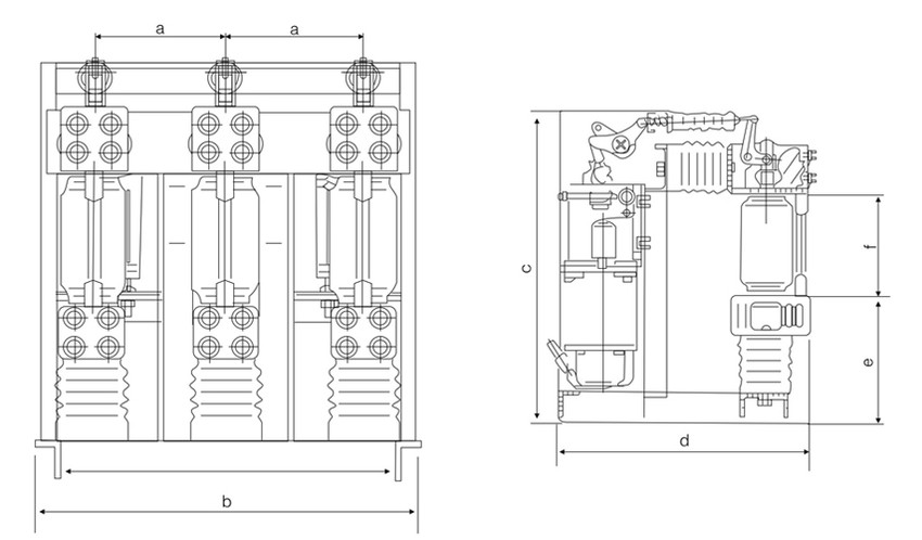
The G fixed type is bolted directly into fixed-type metal-enclosed switchgear, while the A suspended variant and handcart mounting suit handcart-type cubicles. The primary circuit connects to the busbar through terminal clamps and the secondary circuit to the control, protection and measurement loops through the terminal block; the frame and switchgear body must be reliably earthed and all interlocks verified before commissioning.
| Symbol | Dimension |
|---|---|
| a | Pole-unit / phase spacing (front view) |
| b | Overall width of the frame (front view) |
| c | Overall height (side view) |
| d | Overall depth (side view) |
| e | Mechanism / lower section height (side view) |
| f | Upper section height (side view) |