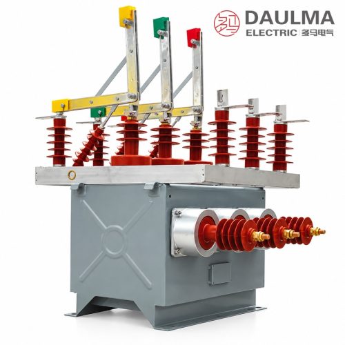
Product Overview
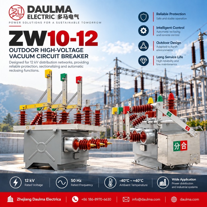
The ZW10-12XDG is an outdoor dual-power automatic transfer switching device built on a 12 kV 50 Hz vacuum circuit breaker with an intelligent controller, for distribution systems fed from two supply sources at rated currents up to 630 A. When the working source fails or drops to undervoltage the unit transfers the load to the healthy source and reverts automatically once the normal source returns, while short-circuit and overcurrent protection with mechanical and electrical interlocks keep the two sources fully isolated.
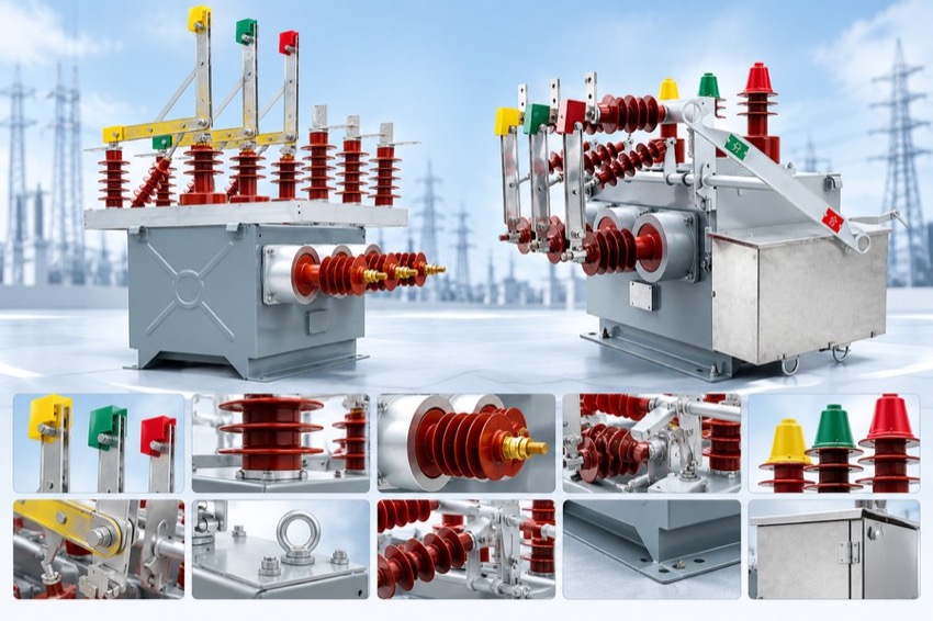
Product Display
Model Designation
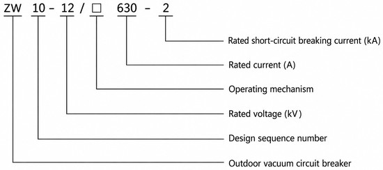
Model format: ZW 10 − 12 XDG
- Z — Vacuum circuit breaker
- W — Outdoor type
- 10 — Design sequence number
- 12 — Rated voltage (kV)
- XDG — Dual-power automatic transfer switching device
Service Conditions
- Ambient air temperature: −40 °C to +40 °C
- Altitude: not exceeding 1000 m (higher altitude on request with derating)
- Earthquake intensity: not exceeding Grade 8
- Relative humidity: daily average ≤ 95%, monthly average ≤ 90%
- Site free from fire, explosion risk, severe pollution, chemical corrosion and violent vibration
Construction
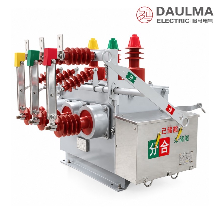
The ZW10-12XDG uses a three-phase column structure with vacuum interrupters housed in a sealed tank on a common base frame. Incoming A-side and B-side terminals serve the two independent power sources, and an external stainless-steel mechanism box houses the spring-storage mechanism, the intelligent controller and the transfer logic.
The intelligent controller monitors both supply sources and performs automatic transfer and reversion, while short-circuit and overcurrent protection together with mechanical and electrical interlocks prevent parallel operation of the two sources. A manual operating handle is provided for emergency operation, and the hermetically sealed interrupters give a long maintenance-free service life outdoors.
Technical Data
| Item | Unit | Value |
|---|---|---|
| Rated Voltage | kV | 12 |
| Highest Operating Voltage | kV | 12 |
| Rated Current | A | 630 |
| Rated Short-Circuit Breaking Current | kA | 20 |
| Rated Short-Circuit Making Current (peak) | kA | 50 |
| Rated Peak Withstand Current | kA | 50 |
| Rated Short-Time Withstand Current | kA | 20 |
| Power Frequency Withstand Voltage (dry) | kV | 42 |
| Lightning Impulse Withstand Voltage (peak) | kV | 75 |
| Rated Operating Sequence | — | O-0.3s-CO-180s-CO |
| Mechanical Life | Operations | 10000 |
| Rated Short-Circuit Breaking Operations | Times | 30 |
| Rated Closing / Opening Voltage of Mechanism | V | 220 |
| Contact Gap | mm | 9 ± 1 |
| Over-Travel | mm | 3 ± 0.5 |
| Three-Phase Opening/Closing Non-Simultaneity | ms | ≤ 2 |
| Contact Closing Bounce Time | ms | ≤ 2 |
| Average Opening Speed | m/s | 1.0 ± 0.2 |
| Average Closing Speed | m/s | 0.7 ± 0.15 |
| Opening Time (max / min operating voltage) | s | 0.015-0.05 / 0.03-0.06 |
| Closing Time | s | 0.025-0.05 |
| Main Circuit Resistance per Phase | μΩ | ≤ 180 |
| Accumulative Allowable Contact Wear | mm | 3 |
Standards
Manufactured and tested in accordance with IEC and GB standards for high-voltage AC circuit breakers, including IEC 62271-100 and GB 1984.
Installation & Dimensions
Installation Diagram
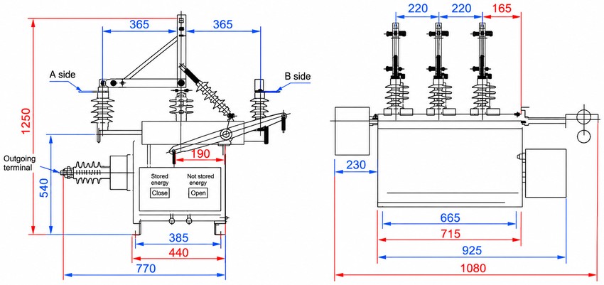
The device is designed for pole-mounted or gantry installation. The A-side and B-side terminals connect the two independent power sources and the outgoing terminal feeds the load; phase spacing and base mounting holes follow the dimensions below.
| View | Item | Dimension (mm) |
|---|---|---|
| Front view | Overall height | 1250 |
| Front view | Lower section height (to outgoing terminal) | 540 |
| Front view | Phase spacing (A-side / centre / B-side) | 365 / 365 |
| Front view | Mechanism box width | 190 |
| Front view | Base mounting hole width | 385 / 440 |
| Front view | Overall base width | 770 |
| Side view | Top bushing spacing | 220 / 220 / 165 |
| Side view | Front overhang depth | 230 |
| Side view | Base length | 665 / 715 / 925 |