Article Content
LAJ-10Q 11kV Cast-Resin Current Transformer for Substation Metering and Protection – IEC 61869-2 Certified
Introduction to the LAJ-10Q Current Transformer
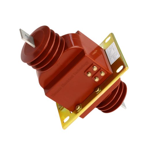
The LAJ-10Q is a high-reliability, cast-resin insulated current transformer (CT) engineered for accurate current measurement and robust protective relay operation in 11kV (IEC standard) or 10kV (domestic system equivalent) medium-voltage networks. Designed in strict compliance with IEC 61869-2 and GB/T 20840.2, this device leverages vacuum pressure impregnation (VPI) epoxy resin technology to encapsulate its magnetic core and windings, ensuring long-term dielectric integrity even under harsh environmental conditions.
Operating Principle of Cast-Resin Insulation
Cast-resin insulation in the LAJ-10Q utilizes a thermosetting epoxy compound processed under vacuum and pressure to eliminate air voids and moisture ingress pathways. This VPI (Vacuum Pressure Impregnation) technique fully saturates the layered GOES (Grain-Oriented Electrical Steel) core and primary/secondary windings, creating a monolithic, non-hygroscopic structure. Unlike oil-filled alternatives, the solid dielectric eliminates fire hazards, leakage risks, and maintenance-intensive oil sampling. The resin’s high tracking resistance (>600 V per IEC 60112) and thermal class F (155°C) rating ensure stable performance across -40°C to +40°C ambient temperatures. Dielectric strength exceeds 42 kV rms for 1 minute at power frequency, satisfying the 28/75 kV (LI/AC) insulation coordination level for 11kV systems per IEC 60071.
Advantages Over Oil-Immersed Designs
Compared to traditional oil-immersed CTs, the LAJ-10Q offers significant operational and safety benefits. Its dry-type construction eliminates flammability concerns, making it suitable for indoor substations, data centers, and confined industrial spaces where fire codes restrict combustible materials. The absence of oil also removes the need for conservator tanks, breather systems, and periodic dielectric fluid testing. Furthermore, the compact mechanical footprint—enabled by higher dielectric strength of epoxy versus oil—reduces space requirements on switchgear panels. Environmental resilience is enhanced: the unit withstands humidity up to 95% RH non-condensing and altitudes up to 1,000 meters without derating. Long-term reliability is demonstrated through accelerated aging tests showing <0.5% change in ratio error after 1,000 thermal cycles (-25°C to +70°C).
Typical Application Overview
The LAJ-10Q serves dual roles in modern power systems: precision metering (accuracy classes 0.2S or 0.5) and high-fidelity protection (classes 5P10, 5P20, or 10P10). It is commonly deployed in utility substations for revenue-grade energy metering and feeder protection, in industrial plants for motor control center (MCC) monitoring, and in renewable integration points (e.g., solar farm collector feeders) where transient immunity is critical. Its robust short-circuit withstand capability—rated for 20 kA for 1 second—ensures survival during fault events without saturation-induced measurement distortion. Secondary terminals are accessible via IP2X-protected compartments, facilitating safe connection to relays, meters, or SCADA interfaces.
Technical Specifications
The LAJ-10Q is engineered to meet stringent electrical and environmental performance criteria essential for reliable operation in 11kV distribution networks. Below is a detailed specification matrix aligned with IEC 61869-2 requirements.
| Parameter | Value |
|---|---|
| Rated System Voltage (Um) | 11 kV (IEC), 10 kV (GB) |
| Rated Primary Current (Ip) | 50 A to 3000 A (standard ratios) |
| Rated Secondary Current (Is) | 1 A or 5 A |
| Accuracy Class (Metering) | 0.2S, 0.5 |
| Accuracy Class (Protection) | 5P10, 5P20, 10P10 |
| Rated Burden (VA) | 2.5 VA to 30 VA (per accuracy class) |
| Insulation Level (AC/LI) | 28 kV rms / 75 kV peak |
| Short-Time Thermal Current | 20 kA for 1 s |
| Dynamic Withstand Current | 50 kA peak |
| Ambient Temperature Range | -40°C to +40°C |
| Relative Humidity | ≤95% RH (non-condensing) |
| Altitude Limit | ≤1,000 m (derating above 1,000 m per IEC 60071-1) |
| Core Material | GOES (Grain-Oriented Electrical Steel), 0.3 mm lamination |
| Insulation System | VPI Epoxy Resin, Thermal Class F (155°C) |
Standard Service Conditions
The LAJ-10Q is rated for continuous operation under standard service conditions defined in IEC 61869-2 Clause 5. These include an ambient temperature range of -40°C to +40°C, with a 24-hour average not exceeding +35°C. Relative humidity may reach 95% provided condensation does not occur on the housing surface—a condition ensured by the hydrophobic nature of the cured epoxy resin. Installation altitude must not exceed 1,000 meters above sea level; for sites between 1,000 m and 3,000 m, the power frequency withstand voltage must be reduced by 1% per 100 m increment above 1,000 m. The transformer assumes symmetrical three-phase operation with balanced loading and sinusoidal waveforms containing ≤5% total harmonic distortion (THD). Operation under DC offset or severe harmonics requires derating or specialized core design.
Electrical Performance Tolerances
Per IEC 61869-2, the LAJ-10Q maintains strict error tolerances under defined operating conditions. For metering class 0.2S, current error must not exceed ±0.2% and phase displacement ≤±10 minutes at 20–120% of rated primary current. Protection class 5P20 guarantees composite error ≤5% at 20 times rated primary current with rated burden connected. Ratio error tolerance is ±0.1% for standard configurations. Burden tolerance is ±10% of stated VA rating. These parameters are validated at 50 Hz or 60 Hz fundamental frequency, with temperature coefficients of error held below 0.005%/°C over the operational range. Saturation characteristics are optimized to maintain linearity up to 25× Ip for protection cores, preventing false tripping during inrush or motor-start transients.
Typical Applications
The LAJ-10Q’s dual-certification (IEC and GB) and robust construction make it suitable for diverse power infrastructure scenarios requiring high accuracy and fault resilience.
Substation Secondary Metering
In 11kV/0.4kV distribution substations, the LAJ-10Q provides revenue-grade current signals to kWh meters and power quality analyzers. Installed on outgoing feeders or main incomers, its 0.2S class ensures billing accuracy compliant with EN 50163 and local utility regulations. The low phase displacement (<5 minutes at 100% Ip) minimizes reactive energy measurement errors. Secondary wiring connects directly to digital meters via shielded twisted-pair cables, with burden kept within 2.5–10 VA to avoid exceeding accuracy limits. In smart grid deployments, multiple LAJ-10Q units feed data concentrators for real-time load profiling and loss analysis.
Industrial Power Distribution
Within manufacturing facilities, the LAJ-10Q monitors critical loads such as large motors, transformers, and rectifier systems. Its 5P20 protection class reliably drives overcurrent and earth-fault relays during short circuits, while the 0.5 metering class supports energy management systems (EMS). The compact size allows retrofit into legacy switchgear without panel modification. In arc-flash mitigation schemes, fast-saturating cores prevent relay misoperation during upstream faults. Units are often installed in MCC rooms with ambient temperatures up to 50°C—handled via thermal derating curves provided in the technical manual.
Renewable Energy Integration
Solar and wind farms utilize the LAJ-10Q on collector feeders connecting inverters or turbines to the 11kV grid interface. Here, the CT must withstand frequent current reversals and harmonic-rich waveforms (up to 15% THD). The GOES core’s low hysteresis loss minimizes heating under distorted currents, while the resin insulation resists partial discharge degradation from high dv/dt transients. Protection-class variants (10P10) coordinate with anti-islanding relays to detect grid disconnection within 200 ms. Outdoor mounting on pole-top platforms is enabled by UV-stabilized resin housing and IP54-rated terminal boxes.
Rural and Suburban Distribution Networks
For utility-owned pole-mounted or pad-mounted transformers serving residential areas, the LAJ-10Q delivers cost-effective metering and basic overcurrent protection. Its maintenance-free design reduces lifecycle costs in remote locations. Standard 5 A secondary output interfaces with electromechanical relays in legacy systems, while 1 A versions suit modern digital relays to minimize copper losses over long cable runs. The unit’s 20 kA short-circuit rating matches typical rural fault levels, ensuring survivability during tree-contact or animal-induced faults.
Compliance with International Standards
The LAJ-10Q is certified to both international and Chinese national standards, ensuring global interoperability and regulatory acceptance.
IEC 61869-2 Compliance Details
IEC 61869-2 governs the performance, testing, and marking of instrument transformers for AC systems >1 kV. The LAJ-10Q meets all mandatory clauses, including dielectric tests (power frequency and lightning impulse), temperature rise limits (<60 K for windings), and accuracy verification under specified burdens. Type tests include short-circuit withstand (20 kA/1s), thermal stability, and partial discharge inception voltage (>10 kV at 1.2 Um/√3). Routine tests performed on every unit include turns ratio verification (±0.1%), polarity check, and insulation resistance (>1,000 MΩ at 2,500 V DC). Markings include rated voltage, ratio, accuracy class, burden, and manufacturer ID per Clause 10.
Alignment with GB/T 20840.2
GB/T 20840.2 is China’s national adoption of IEC 61869-2 with minor modifications. Key differences include the use of 10 kV as the nominal system voltage (vs. 11 kV IEC Um), slightly tighter ratio error tolerances for 0.2S class (±0.15% vs. ±0.2%), and mandatory seismic qualification for regions with PGA ≥0.15g. The LAJ-10Q is dual-marked to satisfy both standards: “11kV” for export markets and “10kV” for domestic Chinese installations. All test reports are issued by CNAS-accredited laboratories, with type test certificates valid for five years.
Testing and Certification Requirements
Certification requires successful completion of type, routine, and sample tests. Type tests—conducted once per design—include temperature rise (verified via resistance method per IEC 60076-2), short-circuit mechanical withstand, and impulse voltage tests (75 kV peak, 1.2/50 μs waveform). Routine tests on every unit encompass insulation resistance, power frequency withstand (28 kV rms for 1 min), and ratio/polarity checks. Sample tests (per batch) validate partial discharge levels (<10 pC at 1.2 Um/√3) and accuracy under extreme temperature. Certificates are issued by notified bodies such as TÜV, SGS, or CEPREI, referencing both IEC 61869-2:2012 and GB/T 20840.2-2014.
On-Site Testing Procedures
Post-installation verification ensures the LAJ-10Q performs within specifications before energization.
Insulation Resistance Test
Using a 2,500 V DC megohmmeter, measure insulation resistance between primary winding and ground, and between secondary windings and ground. Acceptance criterion: ≥1,000 MΩ at 20°C. Correct for temperature using RT2 = RT1 × 2(T1-T2)/10. Low readings indicate moisture ingress or resin cracking—requiring drying or replacement. Perform before and after power frequency withstand test to detect insulation degradation.
Turns Ratio Test
Apply a low-voltage AC source (50–100 V) to the primary and measure secondary voltage. Calculate ratio as Vp/Vs. Compare to nameplate value; tolerance is ±0.1% for metering classes, ±0.5% for protection. Use a dedicated ratio tester (e.g., Omicron CT Analyzer) for automated comparison. Deviations beyond tolerance suggest turn-to-turn shorts or incorrect tap selection.
Polarity Test
Verify reducing polarity per IEC 61869-2 Figure 3. Connect a 1.5 V DC battery momentarily across primary terminals (P1 to P2). Observe secondary voltage spike on a DC voltmeter: positive deflection at S1 confirms correct polarity. Incorrect polarity causes 180° phase shift, leading to relay misoperation or meter reversal. Repeat three times to confirm consistency.
Power Frequency Withstand Voltage Test
Apply 28 kV rms at 50 Hz between primary and ground for 1 minute. Secondary windings are short-circuited and grounded. Monitor for flashover, excessive leakage current (>1 mA), or audible discharge. Failure indicates insulation defect. Use a calibrated test transformer with overcurrent trip set at 50 mA. Conduct only after insulation resistance test confirms dryness.
Short-Circuit Test (for CT)
Inject rated secondary current (1 A or 5 A) into the secondary winding with primary short-circuited. Measure voltage drop across secondary; calculate impedance as Z = V/I. Compare to factory data (typically 0.1–0.5 Ω). Significant deviation suggests core damage or winding deformation. This test validates burden compatibility and verifies no open-circuit risk during operation.
Preventive Maintenance Guide
Although cast-resin CTs are largely maintenance-free, periodic checks extend service life and prevent unexpected failures.
Periodic Inspection Schedule
Conduct visual and electrical inspections annually. Check for surface tracking, cracks, or discoloration on the resin housing. Clean with dry cloth—never solvents. Verify terminal tightness (torque: 2.5 N·m for M6 screws). Measure insulation resistance biennially; values below 500 MΩ warrant investigation. After any system fault exceeding 10 kA, perform full electrical tests regardless of schedule. Document all findings in asset management systems for trend analysis.
Maintenance Intervals and Fault Diagnosis
Table: Recommended Maintenance Intervals for LAJ-10Q
| Interval | Actions |
|---|---|
| Annual | Visual inspection, terminal torque check, IR test |
| 5-Year | Full electrical test suite (ratio, polarity, withstand), partial discharge scan |
| Post-Fault | Immediate ratio and IR test if fault current >10 kA |
Common faults include ratio drift (caused by core aging), open secondary circuits (leading to dangerous overvoltages), and terminal corrosion. Diagnose ratio errors via comparison testing; replace if deviation exceeds 0.3%. Never operate with secondary open—always short before disconnecting loads.
Conclusion
The LAJ-10Q 11kV cast-resin current transformer represents a benchmark in medium-voltage instrumentation, combining IEC 61869-2 and GB/T 20840.2 compliance with field-proven reliability. Its VPI epoxy resin insulation eliminates fire hazards and environmental sensitivity, while the GOES silicon steel core ensures high accuracy across metering (0.2S) and protection (5P20) applications. Rigorous type testing—including 20 kA short-circuit withstand and 75 kV lightning impulse—validates performance under extreme conditions. With a design life of 25–30 years and minimal maintenance requirements, the LAJ-10Q reduces total cost of ownership in substations, industrial plants, and renewable energy sites. Its dual-voltage labeling (11kV/10kV) facilitates global deployment, and standardized terminal configurations simplify integration with modern protection relays and metering systems. As power networks evolve toward digitalization and distributed generation, the LAJ-10Q’s robust transient response and harmonic tolerance ensure continued relevance in next-generation grid architectures.
Frequently Asked Questions (FAQ)
Q1: Can the LAJ-10Q be used in 10kV systems labeled as “10kV” in China?
A: Yes. The LAJ-10Q is dual-rated: 11kV per IEC 61869-2 (Um = 12 kV) and 10kV per GB/T 20840.2. It is fully compatible with Chinese 10kV networks.
Q2: What is the maximum allowable secondary burden for a 5P20 class LAJ-10Q?
A: The rated burden is typically 15 VA or 30 VA—specified on the nameplate. Exceeding this burden increases composite error beyond 5% at 20× Ip, risking protection relay miscoordination.
Q3: Is outdoor installation permitted without additional weatherproofing?
A: Yes. The UV-resistant epoxy housing and IP54-rated terminal box allow direct outdoor mounting. However, secondary terminals should be wired with IP66 gland fittings to prevent moisture ingress.
Q4: How do I verify polarity during commissioning?
A: Use the DC kick test: apply momentary 1.5 V DC to P1–P2; a positive voltage spike at S1 (relative to S2) confirms reducing polarity per IEC standards.
Q5: What happens if the secondary circuit is accidentally opened during operation?
A: Dangerous overvoltages (>2 kV) can develop across the open terminals, risking insulation failure and personnel hazard. Always short-circuit secondary terminals before disconnecting loads. The LAJ-10Q includes internal shorting links for safety during maintenance.