Product Overview
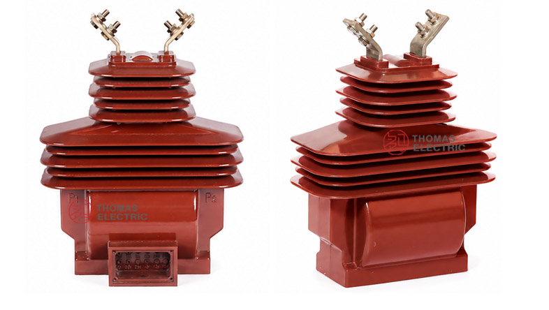
The LZZBW-35A / LZZBW-35B outdoor single-phase current transformer is a 35kV-class outdoor epoxy resin cast instrument transformer designed for current measurement, energy metering and relay protection in high-voltage AC power systems. For international product pages and tender documents, this series should be described as a 35kV / 40.5kV outdoor current transformer, suitable for 50Hz or 60Hz power networks.
This product family is positioned as a 35kV outdoor dry-type epoxy CT for metering and protection applications. It adopts a fully enclosed post-type cast-resin structure, combining high accuracy, strong dynamic thermal stability, moisture resistance and anti-pollution performance. Compared with oil-immersed current transformers, the LZZBW-35A / B is oil-free and easier to maintain. Compared with compact indoor CTs, it is designed for outdoor insulation coordination, long creepage distance and harsh environmental operation.
Product Type


| Item | Specification |
|---|---|
| Product name | Outdoor Single-Phase Epoxy Resin Cast Current Transformer |
| Model | LZZBW-35A / LZZBW-35B |
| Installation condition | Outdoor |
| Phase | Single phase |
| Structure | Fully enclosed post-type / pillar-type epoxy resin cast structure |
| Insulation medium | Outdoor-grade epoxy resin, dry-type insulation |
| Application | Current measurement, energy metering and relay protection |
| International voltage class | 35kV / 40.5kV class high-voltage power system |
| Rated insulation level | 40.5/95/185kV reference; 40.5/95/190kV available by project specification |
| Rated secondary current | 5A or 1A |
| Outdoor service focus | Moisture resistance, anti-pollution performance and high dynamic thermal stability |
Model Explanation

- L: Current transformer.
- Z: Post-type / pillar-type structure.
- Z: Cast-resin insulation.
- B: With protection winding / metering and protection current transformer series.
- W: Outdoor type.
- 35: 35kV rated voltage class, normally matched with 40.5kV highest system voltage.
- A / B: Structure code. A and B are two related outdoor cast-resin CT structures with different secondary winding / terminal arrangement options.
- 5A or 1A: Rated secondary current option.
- Accuracy class: Metering classes such as 0.2S and 0.5, and protection classes such as 10P or 5P, according to project requirements.
Operating Conditions
- Installation place: Outdoor installation for 35kV / 40.5kV power systems.
- Rated frequency: 50Hz or 60Hz.
- Ambient temperature: -40°C to +40°C reference operating range.
- Altitude: ≤ 3000m reference; higher-altitude applications should be confirmed with altitude correction and project insulation requirements.
- Pollution condition: Suitable for outdoor moisture and pollution-resistant insulation applications; creepage distance and pollution class should be confirmed for humid, dusty or coastal areas.
- Installation environment: No severe shock, abnormal vibration, corrosive gas, explosive atmosphere or mechanical load beyond the approved design limits.
- Surface condition: The outdoor resin surface should be kept clean to maintain long-term creepage and insulation reliability.
- Grounding condition: The transformer base and one point of the secondary circuit should be grounded according to the substation grounding design.
Applications
- 35kV / 40.5kV outdoor substations and feeder bays
- Outdoor energy metering and utility billing measurement points
- Current measurement for grid monitoring and power automation systems
- Relay protection for feeders, transformers and capacitor banks
- Industrial and mining enterprise 35kV power distribution systems
- Renewable-energy substations for solar, wind and energy storage projects
- Outdoor grid connection points requiring oil-free instrument transformers
Features
- Outdoor dry-type structure: Fully enclosed epoxy resin casting eliminates transformer oil and reduces leakage-related maintenance concerns.
- 35kV international voltage platform: Suitable for 35kV / 40.5kV outdoor power systems and IEC-style product documentation.
- High accuracy output: Metering classes such as 0.2S and 0.5 can support revenue metering, monitoring and measurement circuits.
- Protection-class capability: 10P and related protection classes support relay protection and fault-current detection.
- Strong thermal and dynamic stability: Short-time thermal current and dynamic current ratings support operation under fault-current conditions.
- Moisture and pollution resistance: Outdoor cast-resin surface and shed structure improve resistance to dirt, humidity and tracking.
- Flexible secondary options: A and B structures can support different accuracy combinations, burdens and secondary circuit configurations.
Operating Principle
The LZZBW-35A / B current transformer converts the high primary current of a 35kV circuit into a standardized secondary current signal, normally 5A or 1A. The secondary output is connected to meters, protection relays, monitoring devices or SCADA systems. The epoxy resin cast body provides insulation between the high-voltage primary circuit and the low-voltage secondary circuits.
For metering circuits, the CT must maintain ratio accuracy and phase displacement within the selected accuracy class and rated burden. For protection circuits, the CT must provide reliable secondary output under short-circuit and fault-current conditions. For this reason, the current ratio, secondary current, rated output, accuracy class, ALF, FS, short-time thermal current and dynamic current should be confirmed together before ordering.
Technical Data
| Parameter | Specification |
|---|---|
| Model | LZZBW-35A / LZZBW-35B |
| Product type | Outdoor single-phase epoxy resin cast current transformer |
| Rated voltage class | 35kV / 40.5kV |
| Rated insulation level | 40.5/95/185kV reference; 40.5/95/190kV by project requirement |
| Rated frequency | 50Hz or 60Hz |
| Rated primary current | 10A to 2000A reference range |
| Rated secondary current | 5A or 1A |
| Accuracy class combination | 0.2S/0.2S, 0.2S/0.5, 0.2S/10P, 0.5/10P, 0.2S/0.5/10P, 0.2/0.5/10P and related combinations |
| Rated output | 10VA, 15VA, 20VA, 30VA or 40VA according to model, ratio and accuracy class |
| Accuracy limit factor | ALF 10 / 15 / 20 reference |
| Instrument security factor | FS 5 or 10 reference |
| Ambient temperature | -40°C to +40°C reference from supplied information |
| Altitude | ≤ 3000m reference; higher altitude by project confirmation |
| Local discharge | Should comply with applicable current transformer standards and project requirements |
| Applicable standards | IEC 61869-1, IEC 61869-2, GB/T 20840.1, GB/T 20840.2; legacy IEC 185 / GB1208 references by agreement |
Selection Table
The following table combines the supplied LZZBW-35A / LZZBW-35B data and reorganizes it for website display. Long headings are split into multiple lines to avoid broken table layout.
| Model | Primary
Current Ratio (A) |
Accuracy
Class |
Output Measuring/ Protective |
ALF | FS | Short-Time ThermalCurrent |
Rated
Dynamic |
|---|---|---|---|---|---|---|---|
| LZZBW-35A | 10–200/5 | 0.2S / 0.2S 0.2S / 0.5 0.2S / 10P 0.5 / 10P 0.2S / 0.5 / 10P 0.2 / 0.5 / 10P |
0.2S: 10VA 0.5: 15VA 10P: 15VA |
10 / 15 / 20 | 5 (10) |
150 × I1n | 375 × I1n |
| 300/5 | 31.5kA | 80kA | |||||
| 400/5 | 31.5kA | 80kA | |||||
| 500/5 | 40kA | 100kA | |||||
| 600/5 | 0.2S: 15VA 0.5: 15VA 10P: 15VA |
10 / 15 / 20 | 50kA | 125kA | |||
| 800/5 | 63kA | 125kA | |||||
| 1000/5 | 0.2S: 15VA 0.5: 15VA 10P: 20VA |
80kA | 160kA | ||||
| 800–2000/5 | 80kA | 160kA | |||||
| LZZBW-35B | 10–200/5 | 0.2S / 0.2S / 0.5 0.2S / 0.5 / 10P 0.2S / 0.5 / 10P / 10P 0.2S / 10P / 10P / 10P |
0.2S: 10VA 0.5: 15VA 10P: 15VA |
10 / 15 / 20 | 5 (10) |
150 × I1n | 375 × I1n |
| 300/5 | 31.5kA | 80kA | |||||
| 400/5 | 31.5kA | 80kA | |||||
| 500/5 | 40kA | 100kA | |||||
| 600/5 | 0.2S: 10VA 0.5: 15VA 10P: 15VA |
50kA | 125kA | ||||
| 800/5 | 63kA | 125kA | |||||
| 1000/5 | 0.2S: 15VA 0.5: 15VA 10P: 20VA |
80kA | 160kA | ||||
| 800–2000/5 | 80kA | 160kA |
Note: The table is for preliminary selection. Final current ratio, rated output, accuracy class, secondary winding quantity, short-time thermal current, dynamic current, ALF and FS shall be confirmed according to the nameplate, approved drawing and factory test report.
Installation and Dimensions

The LZZBW-35A / B should be installed vertically on a stable outdoor foundation, steel structure, pole-mounted support or substation bracket. Before installation, confirm the base mounting holes, primary terminal direction, conductor angle, grounding point, secondary terminal box and required electrical clearance.
| Dimension / Installation Item | Reference Value / Recommended Check Point |
|---|---|
| Installation method | Outdoor vertical mounting on foundation, bracket or steel structure |
| Primary terminal arrangement | Top terminal connection, conductor direction to be confirmed by drawing |
| Secondary terminal box | Lower-side terminal box for metering and protection wiring |
| Mounting base | Base plate / mounting foot structure according to approved drawing |
| Outline dimensions | Refer to approved outline drawing for LZZBW-35A or LZZBW-35B structure |
| Grounding | Transformer base and secondary circuit grounding point must be confirmed before energizing |
| Installation check | Confirm bracket strength, electrical clearance, creepage distance, terminal direction and cable outlet before installation. |
Windings & Terminal Marking
The LZZBW-35A / B product family can be supplied with different secondary winding combinations. The A type is commonly used for two-function metering and protection combinations, while the B type can support more complex multi-secondary combinations according to project requirements. The final terminal arrangement must follow the approved wiring diagram and nameplate.
| Terminal Marking | Function | Application Note |
|---|---|---|
| P1 / P2 | Primary terminals | Used for primary current direction and polarity reference. |
| S1 / S2 | Single secondary winding | Used for one metering or protection output when specified. |
| 1S1 / 1S2 | First secondary winding | Usually assigned to metering or high-accuracy measurement. |
| 2S1 / 2S2 | Second secondary winding | Usually assigned to relay protection. |
| 3S1 / 3S2 | Additional secondary winding | Used for backup protection, independent monitoring or additional metering circuit. |
| 4S1 / 4S2 | Optional fourth winding | Available for multi-function projects when required. |
| Grounding point | Secondary / base grounding | One point of the secondary circuit and transformer base should be grounded according to project practice. |
Standards and Compliance
For new international documentation, the LZZBW-35A / LZZBW-35B current transformer should be specified according to IEC 61869-1 and IEC 61869-2. For Chinese standard documentation, GB/T 20840.1 and GB/T 20840.2 can be used. Older catalogues may mention IEC 185, GB1208 or GB1208-1997; these can be kept only as legacy references when required by tenders or comparison documents.
Safety Notes
- Confirm voltage class, insulation level, current ratio, secondary current, accuracy class and rated burden before installation.
- Check P1 / P2 polarity and secondary terminal marking before connecting meters or protection relays.
- Confirm outdoor electrical clearance, creepage distance, mounting strength and conductor mechanical load before energizing.
- Ground the transformer base and one point of the secondary circuit according to the substation grounding design.
- The CT secondary circuit must not be open-circuited while primary current is flowing.
- Before disconnecting meters, relays or test equipment, short-circuit the secondary circuit with an approved shorting device.
- Seal the secondary terminal box after wiring to reduce moisture ingress and maintain outdoor reliability.
- Installation and commissioning shall be performed by qualified high-voltage electrical personnel.
Ordering Info
| Item | Options / Examples |
|---|---|
| Model | LZZBW-35A or LZZBW-35B |
| Rated voltage class | 35kV / 40.5kV |
| Rated insulation level | 40.5/95/185kV or 40.5/95/190kV by project requirement |
| Rated primary current | 10A, 100A, 200A, 300A, 400A, 600A, 800A, 1000A, 1500A, 2000A or customized |
| Rated secondary current | 5A or 1A |
| Accuracy class and burden | 0.2S, 0.5, 10P, 5P; 10VA, 15VA, 20VA, 30VA, 40VA or project-specific |
| ALF / FS | ALF 10 / 15 / 20; FS 5 or 10 according to project requirement |
| Secondary winding quantity | Measurement winding, protection winding, or multiple secondary winding configurations |
| Outdoor environment | Altitude, pollution class, creepage distance, humidity, coastal condition and temperature range |
| Documentation | Outline drawing, wiring diagram, routine test report, certificate, label language and packing requirement |