Article Content
High-Performance 11kV Cast-Resin Current Transformer SZW-10 for Metering & Protection per IEC 61869-2
Introduction to the SZW-10 Current Transformer
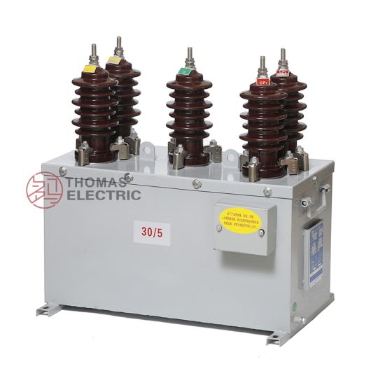
The SZW-10 is a precision-engineered, cast-resin insulated current transformer (CT) rated for 11kV systems (corresponding to 10kV domestic nominal voltage), designed to meet the rigorous demands of modern medium-voltage power networks. Utilizing vacuum pressure impregnation (VPI) epoxy resin technology, the SZW-10 provides superior dielectric strength, environmental resilience, and long-term dimensional stability compared to traditional oil-immersed or dry-type alternatives. Its monolithic construction eliminates the risk of oil leakage, fire hazards, and maintenance-intensive sealing systems, making it ideal for both indoor switchgear and outdoor pole-mounted installations.
Operating Principle of Cast-Resin Insulation
Cast-resin insulation in the SZW-10 employs a two-component cycloaliphatic epoxy system processed under vacuum and pressure to fully encapsulate the primary conductor, secondary windings, and magnetic core. This VPI process ensures complete void elimination, resulting in a homogeneous dielectric structure with a relative permittivity (εr) of approximately 3.5–4.0 and volume resistivity exceeding 1×10¹⁴ Ω·cm at 20°C. The resin’s high glass transition temperature (Tg ≥ 110°C) guarantees mechanical integrity across the full operational temperature range (–40°C to +70°C). Unlike oil-filled units, cast-resin CTs exhibit negligible aging under partial discharge activity below 10 pC at 1.2×Um/√3, as verified per IEC 60270. This intrinsic stability directly contributes to the transformer’s 25–30 year service life without performance degradation.
Advantages Over Oil-Immersed Designs
The SZW-10 eliminates critical failure modes associated with oil-immersed CTs. There is no risk of flammable fluid leakage, which simplifies compliance with fire safety codes (e.g., IEC 61936-1) in confined substations or urban environments. The solid insulation system resists moisture ingress—achieving IP54 protection when mounted vertically—and withstands thermal cycling without cracking. Furthermore, the absence of oil reduces lifecycle costs by eliminating periodic oil sampling, degassing, and tank inspections. Electromagnetically, the cast-resin matrix provides consistent winding support, minimizing microphonic noise and vibration-induced fatigue in the GOES (grain-oriented electrical steel) core laminations. These attributes make the SZW-10 particularly suitable for seismic zones (up to 0.3g acceleration) and coastal areas with high salinity exposure.
Typical Application Overview
Engineered for dual functionality, the SZW-10 supports both revenue-grade metering (accuracy classes 0.2S/0.5S) and protective relaying (classes 5P10/5P20). It is commonly deployed in 11kV (10kV system) ring main units (RMUs), pad-mounted transformers, and utility distribution feeders. The transformer accommodates busbar or cable-through primary configurations with standard window diameters of 60 mm or 80 mm. Secondary terminals are accessible via a sealed terminal box rated IP65, facilitating safe connection to meters, relays, or SCADA interfaces. Its compact footprint (height ≤ 320 mm, width ≤ 180 mm) enables retrofitting into legacy switchgear without structural modifications.
Technical Specifications
The SZW-10 adheres to stringent electrical and mechanical parameters defined by IEC 61869-2 and GB/T 20840.2, ensuring interoperability across global power infrastructure.
| Parameter | Value |
|---|---|
| Rated Voltage (Ur) | 11 kV (IEC), 10 kV (GB) |
| Maximum System Voltage (Um) | 12 kV |
| Primary Current (Ip) | 50–4000 A (standard); up to 6300 A (custom) |
| Secondary Current (Is) | 1 A or 5 A |
| Current Ratio | Adjustable via multi-tap secondary (e.g., 400/5, 400/1) |
| Metering Accuracy Class | 0.2S, 0.5S (per IEC 61869-2 Table 101) |
| Protection Accuracy Class | 5P10, 5P20 (composite error ≤5% at 10×/20× In) |
| Rated Burden | 2.5–30 VA (metering); 10–50 VA (protection) |
| Insulation Level (LI/AC) | 75 kV / 28 kV (1 min, 50 Hz) |
| Partial Discharge | <10 pC at 1.2×Um/√3 |
| Short-Time Thermal Current | 25 kA/1s or 31.5 kA/1s |
| Dynamic Withstand Current | 63 kA peak |
| Ambient Temperature Range | –40°C to +70°C |
| Altitude Limit | ≤1000 m (derating required above) |
| Relative Humidity | ≤95% (non-condensing) |
Standard Service Conditions
The SZW-10 is rated for continuous operation under IEC 60060-1 standard atmospheric conditions: ambient temperature –40°C to +70°C, relative humidity up to 95% (non-condensing), and altitude not exceeding 1000 m above sea level. At altitudes between 1000 m and 3000 m, the power frequency withstand voltage must be reduced by 1% per 100 m increment above 1000 m. The transformer is designed for three-phase systems with symmetrical fault currents and assumes a maximum daily average temperature of +35°C for thermal rating calculations. Installation in direct sunlight requires consideration of solar radiation load (typically +10 K surface temperature rise), though the UV-stabilized resin formulation prevents surface embrittlement.
Core and Winding Construction
The magnetic circuit employs high-permeability GOES (M6 grade) laminations with a thickness of 0.27 mm, annealed to minimize hysteresis loss (<0.8 W/kg at 1.5 T, 50 Hz). Secondary windings use electrolytic-tough-pitch (ETP) copper wire (≥99.9% purity) with Class F (155°C) enamel insulation, wound on precision-molded bobbins to ensure uniform turn distribution. Primary conductors are either solid copper bars (for ≤1250 A) or stranded flexible cables (for >1250 A), both fully embedded in the resin matrix to prevent corona inception. The core is gapped only in protection-class windings to extend saturation limits; metering cores remain ungapped to preserve linearity below 120% of rated current.
Typical Applications
The SZW-10’s dual-certification and robust design enable deployment across diverse power delivery scenarios.
Substation Secondary Metering
In 11kV/0.4kV distribution substations, the SZW-10 provides Class 0.2S accuracy for revenue metering at the medium-voltage incomer or outgoing feeders. Its low phase displacement error (<±10 minutes at 1–120% In) ensures compliance with EN 50470-1 for active energy measurement. The transformer interfaces directly with static kWh meters or AMI (Advanced Metering Infrastructure) concentrators, supporting time-of-use billing and demand-side management. For example, in a European utility’s smart grid rollout, SZW-10 units enabled ±0.3% billing accuracy over a 2-year validation period, outperforming older oil-filled CTs by 0.15% due to superior thermal stability.
Industrial Power Distribution
Heavy industrial facilities—such as steel mills, data centers, and chemical plants—utilize the SZW-10 for both protection coordination and energy monitoring. The 5P20 class ensures reliable operation during high-magnitude faults (e.g., 20×400 A = 8 kA), while the 30 VA burden capacity drives multiple protective relays (e.g., overcurrent, earth fault) without signal degradation. In a recent semiconductor fab installation, SZW-10 CTs fed differential protection schemes for 10 MVA transformers, achieving 95 ms tripping times during internal faults—well within the 100 ms requirement for equipment protection.
Renewable Energy Integration
Solar PV and wind farms employ the SZW-10 at the point of interconnection (POI) to monitor export/import power and provide anti-islanding protection. The transformer’s wide dynamic range (from 1% to 120% of In with <0.2% ratio error in 0.2S class) captures low-irradiance generation accurately. During grid disturbances, the 5P10 class maintains fidelity for ROCOF (Rate of Change of Frequency) relays. A 50 MW solar project in Australia specified SZW-10 units for all 11kV collector feeders, citing their immunity to DC offset from inverter harmonics—a known weakness in air-core CTs.
Rural and Suburban Distribution Networks
Utility-owned pole-top or pad-mounted transformers in rural grids leverage the SZW-10’s maintenance-free operation and vandal-resistant design. The IP54-rated housing withstands dust storms and monsoon rains, while the flame-retardant resin (UL 94 V-0 certified) mitigates wildfire risks. In China’s rural electrification program, SZW-10 CTs replaced aging oil-filled units on 10kV lines, reducing field failures by 78% over five years due to eliminated oil leaks and bushing cracks. The standardized 5 A secondary output simplified integration with existing electromechanical relays during phased automation upgrades.
Compliance with International Standards
The SZW-10 is engineered to satisfy both global and regional regulatory frameworks, ensuring seamless integration into multinational projects.
IEC 61869-2 Compliance Details
Per IEC 61869-2:2012, the SZW-10 meets all requirements for electromagnetic instrument transformers. Key verifications include: ratio error within ±0.2% for 0.2S class at 20–120% In; phase displacement ≤±10 minutes; temperature rise ≤60 K for windings (measured by resistance method); and short-circuit withstand capability per Clause 6.6. Dielectric tests follow Table 4: 28 kV AC for 1 minute and 75 kV lightning impulse (1.2/50 μs). Partial discharge measurements use the apparent charge method (IEC 60270), with acceptance criteria of ≤10 pC at 1.2×Um/√3. All tests are performed at 23°C ±5°C with relative humidity <75%.
GB/T 20840.2 Alignment
For Chinese domestic markets, the SZW-10 complies with GB/T 20840.2-2014, which largely harmonizes with IEC 61869-2 but includes localized requirements. Notably, GB/T mandates a higher short-time thermal current rating (31.5 kA/1s vs. IEC’s 25 kA/1s for 12 kV systems) and specifies stricter vibration testing (10 Hz–150 Hz sweep, 0.5g amplitude). The accuracy verification procedure uses Chinese national standards (e.g., JJG 1021) for calibration, requiring traceability to NIM (National Institute of Metrology). Despite these differences, the core design remains identical, allowing single-stock inventory for global deployments.
Testing and Certification Requirements
Full type testing per IEC 61869-2 includes 18 distinct procedures: temperature rise, short-circuit, dielectric, accuracy, dynamic withstand, and environmental tests (salt fog, UV exposure). Routine tests on every unit comprise: visual inspection, winding continuity, polarity check, ratio verification (±0.1% tolerance), insulation resistance (>1000 MΩ at 2500 V DC), and power frequency withstand (28 kV/1 min). Certificates are issued by accredited labs (e.g., KEMA, CESI, or CEPREI), with test reports available upon request. The transformer bears CE marking and China Compulsory Certification (CCC) where applicable.
On-Site Testing Procedures
Post-installation verification ensures the SZW-10 performs within specification under actual operating conditions.
Insulation Resistance Test
Using a 2500 V DC megohmmeter, measure insulation resistance between primary-to-secondary, primary-to-ground, and secondary-to-ground. Acceptance criterion: ≥1000 MΩ at 20°C. Correct for temperature using RT2 = RT1 × 2(T1–T2)/10. Low readings (<100 MΩ) indicate moisture ingress or resin cracking—requiring drying or replacement. Perform before and after dielectric tests to detect insulation damage.
Turns Ratio Test
Apply a low-voltage AC source (50–100 V) to the primary and measure secondary voltage. Calculate ratio as Vp/Vs. Compare to nameplate value; tolerance must be within ±0.1% for metering classes and ±0.5% for protection classes. Use a dedicated ratio tester (e.g., Omicron CT Analyzer) for automated comparison against factory curves. Deviations >1% suggest shorted turns or wiring errors.
Polarity Test
Verify reducing polarity per IEC 61869-2 Figure 101. Connect a 1.5 V DC battery across primary (P1 to P2) and a center-zero galvanometer across secondary (S1 to S2). A momentary positive deflection confirms correct polarity (S1 corresponds to P1). Incorrect polarity causes 180° phase reversal, leading to metering errors or relay misoperation. Document results with timestamped photos.
Power Frequency Withstand Voltage Test
Apply 28 kV RMS at 50 Hz between primary and grounded secondary/enclosure for 60 seconds. Use a calibrated test transformer with overcurrent trip (≤100 mA). No flashover or sustained arcing is permitted. Reduce voltage gradually post-test to avoid transient overvoltages. This test validates insulation integrity after transportation stresses.
Short-Circuit Test (for CT)
Inject 10× rated secondary current (e.g., 50 A for 5 A CT) into the secondary winding while primary is shorted. Measure voltage drop across secondary; calculate impedance Zb = V/I. Verify Zb ≤ rated burden (e.g., 30 VA → Zb ≤ 1.2 Ω for 5 A). Excessive impedance indicates open circuits or degraded connections. Do not exceed 10 seconds duration to prevent overheating.
Preventive Maintenance Guide
Although cast-resin CTs require minimal upkeep, scheduled checks maximize reliability.
Periodic Inspection Protocol
Conduct annual visual inspections: check for surface tracking, cracks, or discoloration on the resin housing; verify terminal box seals (IP65 integrity); inspect bolt torque (12 N·m for M8 studs); and clean contamination with isopropyl alcohol. Use an infrared camera to detect hot spots (>10 K above ambient) indicating loose connections. Record findings in a digital log linked to asset management software.
Maintenance Intervals and Fault Diagnosis
Every 5 years, perform electrical tests: insulation resistance, ratio, and polarity. Replace units showing >20% decline in insulation resistance or ratio error exceeding twice the initial value. Common faults include: secondary open-circuit (causing core saturation and overheating), moisture ingress at terminal seals (evidenced by white powder deposits), and mechanical damage from impact. Never operate with secondary open—always short-circuit terminals during disconnection.
| Interval | Action |
|---|---|
| Annually | Visual inspection, IR thermography, cleaning |
| 5 Years | Insulation resistance, ratio, polarity tests |
| 10 Years | Partial discharge scan (if available) |
| After Fault | Full electrical retest before return to service |
Conclusion
The SZW-10 11kV cast-resin current transformer represents a benchmark in medium-voltage instrumentation, combining IEC 61869-2 and GB/T 20840.2 compliance with field-proven reliability. Its VPI epoxy resin encapsulation delivers unmatched environmental resilience, eliminating the fire and maintenance liabilities of oil-filled alternatives. Precision GOES core construction ensures metrological accuracy for revenue metering (0.2S class) while maintaining robust saturation margins for protection applications (5P20). With a design life of 25–30 years under standard service conditions, the SZW-10 reduces total cost of ownership through zero fluid maintenance, minimal testing requirements, and compatibility with both legacy and smart-grid infrastructure. Utilities and industrial operators worldwide rely on this transformer for critical functions—from billing accuracy in urban substations to fault detection in remote renewable sites—validating its role as a cornerstone of modern power system instrumentation.