Article Content
For Substation Metering & Protection: XGW-12 11kV Cast-Resin Voltage Transformer per IEC 61869-3
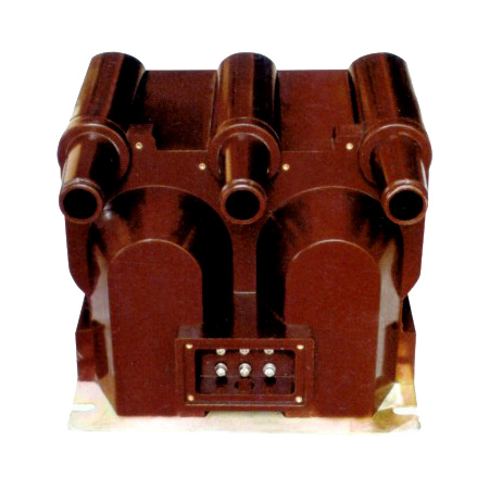
Introduction to the XGW-12 Voltage Transformer
The XGW-12 is a medium-voltage instrument transformer engineered specifically as a voltage transformer (VT) for accurate voltage measurement and reliable protective relay operation in 11kV (IEC) / 10kV (domestic) power systems. As a critical interface between high-voltage primary circuits and low-voltage secondary instrumentation, it ensures safe, standardized signal conversion while maintaining galvanic isolation. Its design leverages modern cast-resin insulation technology, offering significant operational advantages over traditional oil-immersed alternatives.
Operating Principle of Cast-Resin Insulation
Cast-resin insulation in the XGW-12 employs vacuum pressure impregnation (VPI) with cycloaliphatic epoxy resin, fully encapsulating the primary and secondary windings along with the magnetic core. This monolithic structure eliminates air voids and moisture ingress pathways, providing superior dielectric strength and partial discharge resistance. The resin’s high thermal conductivity (0.8–1.2 W/m·K) enables efficient heat dissipation from copper losses, supporting continuous operation at rated load without thermal degradation. Unlike oil-filled units, there is no risk of leakage, fire hazard, or environmental contamination, making it ideal for indoor substations, urban installations, and environmentally sensitive areas. The solid insulation also exhibits excellent mechanical rigidity, resisting vibration-induced winding displacement during short-circuit events.
Advantages Over Oil-Immersed Designs
Compared to oil-immersed VTs, the XGW-12’s cast-resin construction delivers enhanced safety, reduced maintenance, and greater installation flexibility. It is inherently non-flammable (meeting IEC 60695 flammability class V-0), eliminating fire suppression requirements. With no liquid dielectric, there are no oil sampling, degassing, or level monitoring tasks—reducing lifecycle costs by up to 40% over 25 years. The compact footprint (typically 30% smaller than equivalent oil units) allows for space-constrained retrofits in existing switchgear bays. Furthermore, cast-resin VTs exhibit lower temperature rise (<55 K at rated output per IEC 61869-3), ensuring stable accuracy under varying ambient conditions. They are also immune to altitude derating below 1,000 m, whereas oil units may require correction factors above 1,000 m due to reduced dielectric strength.
Typical Applications Overview
The XGW-12 is deployed across utility distribution networks, industrial facilities, and renewable energy plants where precise voltage transformation is essential. Primary applications include revenue metering in 11kV ring-main units, overvoltage/undervoltage protection in feeder relays, synchro-check functions in generator synchronization, and harmonic monitoring in power quality analyzers. Its dual-winding configuration (e.g., 0.2/3P accuracy classes) supports simultaneous metering and protection functions without cross-interference. In smart grid deployments, it interfaces with digital IEDs (Intelligent Electronic Devices) via analog inputs, enabling real-time SCADA telemetry. The transformer’s robustness against transient overvoltages (BIL 75 kV) makes it suitable for networks with frequent switching surges or lightning exposure.
Technical Specifications
The XGW-12 adheres to stringent electrical and mechanical parameters defined by IEC 61869-3 and GB/T 20840.3, ensuring interoperability and long-term reliability in diverse operating environments.
| Parameter | Value |
|---|---|
| Primary Voltage (IEC) | 11 kV / √3 (phase-to-earth) |
| Primary Voltage (Domestic) | 10 kV / √3 (phase-to-earth) |
| Secondary Voltage | 100 V / √3 or 110 V / √3 (standard); 100 V or 110 V (line-to-line optional) |
| Voltage Ratio | (11,000/√3) : (100/√3) = 110:1 (typical) |
| Accuracy Class | Metering: 0.2, 0.5; Protection: 3P, 6P |
| Rated Output (per winding) | 25 VA, 50 VA, 100 VA (at specified accuracy class) |
| Burden Power Factor | 0.8 lagging (standard) |
| Insulation Level (Um) | 12 kV |
| Lightning Impulse Withstand (BIL) | 75 kV peak |
| Power Frequency Withstand | 28 kV rms, 1 min (dry), 32 kV rms (wet) |
| Partial Discharge | <10 pC at 1.2 × Um/√3 |
| Core Material | Grain-Oriented Electrical Steel (GOES), M4 grade, 0.27 mm lamination |
| Temperature Rise | <55 K (windings), <60 K (core) at rated output |
| Ambient Temperature Range | –25°C to +40°C (standard); –40°C to +55°C (extended) |
| Relative Humidity | Up to 95% non-condensing |
| Altitude Limit | ≤1,000 m (no derating); >1,000 m requires voltage correction per IEC 60071 |
Standard Service Conditions
The XGW-12 is rated for continuous operation under standard service conditions per IEC 61869-3: ambient temperature from –25°C to +40°C, relative humidity up to 95% (non-condensing), and installation altitude not exceeding 1,000 meters above sea level. At altitudes between 1,000 m and 2,000 m, the power frequency withstand voltage must be reduced by 1% per 100 m increment above 1,000 m. For example, at 1,500 m, the test voltage becomes 28 kV × (1 – 0.05) = 26.6 kV. The transformer is designed for three-phase systems with neutral grounding via Petersen coil, solidly grounded, or ungrounded configurations. It withstands system overvoltages up to 1.1 × Um continuously and transient overvoltages per IEC 60071 coordination curves.
Electrical Performance Parameters
Key electrical characteristics include a voltage error of ≤±0.2% and phase displacement of ≤±10 minutes at 0.2 accuracy class under 25–100% of rated burden. For protection class 3P, composite error remains within ±3% at 5% to 100% of rated voltage and up to 100% of rated burden. The magnetizing current is typically <0.5% of rated primary current at nominal voltage, minimizing core saturation during fault conditions. Thermal stability is verified through a 2-hour temperature rise test at 1.2 × rated output, confirming that hotspot temperature does not exceed 120°C. The secondary terminals are rated for 10 A continuous and 50 A for 1 second during short-circuit events, complying with terminal thermal withstand requirements in IEC 61869-3 Clause 7.4.
Typical Applications
The XGW-12 voltage transformer serves as a foundational component in modern power systems, enabling accurate measurement and dependable protection across multiple sectors.
Substation Secondary Metering
In 11kV primary substations, the XGW-12 provides the voltage input for revenue-class kWh meters, demand recorders, and power factor controllers. Its 0.2 accuracy class ensures compliance with regulatory metering standards (e.g., EN 50470-3). The transformer is typically connected phase-to-earth on each of the three phases, feeding a wye-connected secondary circuit to a multi-function meter. To prevent ferroresonance—a risk in isolated neutral systems—the secondary circuit includes a damping resistor (typically 100–500 Ω) or is connected to a minimum burden of 10 VA. In digital substations, the analog output interfaces with merging units for IEC 61850-9-2 LE sampled value transmission.
Industrial Power Distribution
Within manufacturing plants and process facilities, the XGW-12 monitors voltage stability for motor control centers (MCCs) and variable frequency drives (VFDs). Undervoltage protection relays use its secondary signal to trip motors during sag events, preventing mechanical damage. In arc furnace or welding plant environments with high harmonic distortion, the GOES core minimizes additional losses from 3rd, 5th, and 7th harmonics. The transformer’s high short-circuit withstand capability (withstanding 25 kA for 1 second on primary) ensures survival during downstream faults. Installation inside metal-enclosed switchgear complies with IP2X finger-safe requirements, with secondary terminals accessible via insulated test blocks for calibration without de-energization.
Renewable Energy Integration
Solar photovoltaic (PV) and wind farms utilize the XGW-12 for grid synchronization and anti-islanding protection. During islanding events, voltage and frequency deviations detected via the VT trigger disconnection within 2 seconds per IEEE 1547. The transformer’s fast response time (<20 ms to 90% of final value during step changes) supports rapid relay operation. In PV inverters, it feeds voltage signals to maximum power point tracking (MPPT) algorithms. Due to frequent cloud-induced irradiance fluctuations, the VT must maintain accuracy under rapidly varying loads—achieved through low remanence in the GOES core and tight winding tolerances. Ground-fault detection in ungrounded collector systems also relies on residual voltage measurement from open-delta VT connections.
Rural and Suburban Distribution Networks
In overhead line-fed rural feeders, the XGW-12 is pole-mounted or housed in pad-mounted transformers for remote metering and sectionalizing. Its cast-resin housing resists UV degradation, salt spray (tested per IEC 60068-2-52), and pollution (creepage distance ≥25 mm/kV for light pollution zones). For cost-effective deployment, single-phase units are used in two-VT V-V configurations, reducing capital expenditure while maintaining acceptable accuracy for billing. The transformer supports AMI (Advanced Metering Infrastructure) backhaul via cellular or RF mesh networks, with secondary outputs scaled to match concentrator input ranges. Maintenance crews perform annual visual inspections for surface tracking or corona damage, especially in coastal or industrial atmospheres.
Compliance with International Standards
The XGW-12 is engineered to meet the rigorous requirements of global and regional standards governing instrument transformer performance, safety, and testing.
IEC 61869-3 Compliance Details
IEC 61869-3:2011 specifies performance criteria for inductive voltage transformers for measurement and protection. The XGW-12 complies with all mandatory clauses, including accuracy limits (Table 2), insulation tests (Clause 6), temperature rise (Clause 7), and short-circuit withstand (Clause 8). Notably, it satisfies the composite error requirement for protection class 3P: |εc| ≤ 3% when subjected to 5%–100% of rated voltage and 25%–100% of rated burden at power factor 0.8 lagging. Dielectric tests include 1-minute power frequency withstand at 28 kV and lightning impulse at 75 kV with wave shape 1.2/50 μs. Partial discharge measurements are conducted per IEC 60270, with acceptance criteria of <10 pC at 1.2 × Um/√3. The standard also mandates marking of polarity (reducing polarity per IEC 61869-1 Annex A), which is permanently embossed on the nameplate.
GB/T 20840.3 Alignment
China’s national standard GB/T 20840.3-2013 aligns closely with IEC 61869-3 but includes localized requirements. Key differences include: (1) mandatory wet AC withstand test at 32 kV for outdoor types, (2) stricter creepage distance requirements (≥31 mm/kV for heavy pollution zones III/IV), and (3) requirement for secondary terminal short-circuit proofing (withstand 50 A for 1 s). The XGW-12 meets these through enhanced resin formulation with hydrophobic additives and reinforced terminal blocks. Additionally, GB/T 20840.3 specifies factory routine tests for every unit—including ratio verification and insulation resistance—whereas IEC permits type tests for batch certification. All XGW-12 units shipped to China undergo 100% routine testing per GB/T 20840.3 Clause 12.
Testing and Certification Requirements
Certification involves type tests, routine tests, and special tests. Type tests (performed once per design) include temperature rise, short-circuit withstand, and impulse tests. Routine tests (per unit) cover winding resistance, ratio error, polarity, and power frequency withstand. Special tests—such as partial discharge mapping or seismic withstand (for earthquake-prone regions)—are available on request. The XGW-12 carries certification marks from CQC (China Quality Certification) and is listed in international directories such as KEMA and CESI. Test reports include traceable calibration data from accredited labs (ISO/IEC 17025), with uncertainty budgets for ratio and phase error measurements.
On-Site Testing Procedures
Post-installation verification ensures the XGW-12 performs within specifications before energization. All tests follow IEC 61869-3 and IEEE C57.13 guidelines.
Insulation Resistance Test
Using a 2,500 V DC megohmmeter, measure insulation resistance between primary winding and ground, secondary winding and ground, and primary-to-secondary. Acceptance criteria: ≥1,000 MΩ at 20°C. Correct for temperature using RT2 = RT1 × 2((T1–T2)/10). Low readings indicate moisture ingress or resin cracking. Perform before and after dielectric tests to detect insulation degradation.
Turns Ratio Test
Apply 100–200 V AC to the primary and measure secondary voltage. Calculate actual ratio = Vp/Vs. Compare to nameplate ratio; tolerance must be within ±0.2% for 0.2 class. Use a dedicated ratio tester (e.g., Omicron CT Analyzer) for precision. Deviations >0.5% suggest winding shorts or incorrect tap selection.
Polarity Test
Verify reducing polarity per IEC 61869-1: momentarily apply DC to primary (H1+, H2–); observe secondary voltage spike direction. If X1 shows positive deflection when H1 is energized, polarity is correct. Incorrect polarity causes 180° phase shift, leading to metering errors or relay misoperation in differential schemes.
Power Frequency Withstand Voltage Test
Apply 28 kV rms (11kV system) at 50 Hz between primary and ground for 1 minute. Secondary windings are short-circuited and grounded. Monitor for flashover, excessive leakage current (>1 mA), or audible discharge. Wet test (for outdoor units) uses artificial rain per IEC 60060-1. Failure indicates insulation defects or contamination.
Open-Circuit Test (Voltage Transformer Specific)
With secondary open, apply 100%, 110%, and 120% of rated primary voltage. Measure no-load current and secondary voltage. No-load current should be <0.5% of rated primary current. Excessive current indicates core saturation or inter-turn faults. Secondary voltage must remain linear; deviation >1% suggests core nonlinearity or winding issues.
Preventive Maintenance Guide
Proactive maintenance extends service life and prevents unexpected failures in critical infrastructure.
Periodic Inspection Schedule
Conduct visual inspections annually: check for surface cracks, tracking marks, terminal corrosion, or resin discoloration. Clean housing with non-abrasive detergent if contaminated. Every 5 years, perform electrical tests (insulation resistance, ratio, polarity). After major system faults (e.g., short-circuit currents >10 kA), conduct immediate post-event testing. In coastal or chemical plants, increase inspection frequency to semi-annual due to accelerated aging from salt or SO2.
Maintenance Intervals and Fault Diagnosis
| Interval | Action | Fault Indicators |
|---|---|---|
| Annual | Visual inspection, terminal torque check (8 N·m) | Cracks, carbon tracking, loose bolts |
| 5 Years | Full electrical test suite (IR, ratio, PD) | IR <500 MΩ, ratio error >0.3% |
| After Fault | Open-circuit test, IR test | Elevated no-load current, burnt smell |
| 10 Years | Thermal imaging under load | Hotspots >10 K above ambient |
Common faults include partial discharge (audible buzzing, ozone smell), secondary winding opens (meter zero reading), and core saturation (distorted waveform on oscilloscope). Replace if PD exceeds 20 pC or insulation resistance drops below 200 MΩ.
Conclusion
The XGW-12 11kV cast-resin voltage transformer represents a benchmark in medium-voltage instrumentation, combining precision engineering with robust construction for demanding substation and industrial environments. Its compliance with IEC 61869-3 and GB/T 20840.3 ensures global interoperability, while the VPI epoxy resin insulation system delivers unmatched safety, environmental resilience, and minimal lifecycle maintenance compared to oil-filled alternatives. The use of high-permeability GOES core material guarantees stable accuracy across metering (0.2 class) and protection (3P class) applications, even under harmonic-rich or transient-laden conditions. With a design service life exceeding 25–30 years—validated through accelerated aging tests per IEC 60216—the XGW-12 offers exceptional total cost of ownership. Its compact form factor facilitates retrofitting into legacy switchgear, and standardized secondary outputs ensure seamless integration with modern digital relays, meters, and SCADA systems. For utilities and industrial operators seeking a reliable, future-proof voltage sensing solution that meets both international standards and local grid codes, the XGW-12 provides a technically superior and economically sound choice. Regular adherence to the outlined on-site testing and preventive maintenance protocols further safeguards performance integrity throughout its operational lifespan, minimizing unplanned outages and ensuring continuous compliance with regulatory accuracy requirements.