Article Content
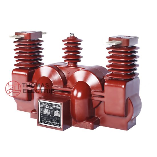
For Substation Metering & Protection: SZV-10K 11kV Cast-Resin Voltage Transformer per IEC 61869-3
Introduction to the SZV-10K Voltage Transformer
The SZV-10K is a precision-engineered, cast-resin insulated voltage transformer (VT) designed for reliable operation in 11 kV (IEC nominal) or 10 kV (domestic system) medium-voltage distribution networks. As a critical interface between high-voltage primary circuits and low-voltage secondary instrumentation, it provides galvanically isolated, scaled-down voltage signals for accurate metering, real-time monitoring, and protective relay coordination. Its robust construction leverages modern epoxy resin vacuum pressure impregnation (VPI) technology, ensuring long-term dielectric integrity even under harsh environmental conditions.
Operating Principle of Cast-Resin Insulation
Cast-resin insulation in the SZV-10K employs a thermosetting epoxy resin system that fully encapsulates the primary and secondary windings along with the magnetic core. During manufacturing, the coil assembly undergoes vacuum degassing followed by pressure impregnation (VPI), eliminating air voids and moisture ingress pathways. This monolithic structure provides superior partial discharge resistance (<5 pC at 1.2 × Ur), excellent tracking resistance (CTI > 600 V), and mechanical rigidity. Unlike oil-filled units, the solid dielectric eliminates fire hazards, leakage risks, and maintenance associated with fluid containment. The resin’s coefficient of thermal expansion closely matches that of copper and silicon steel, minimizing stress during thermal cycling from –40°C to +40°C ambient operation.
Advantages Over Oil-Immersed Designs
Compared to traditional oil-immersed VTs, the SZV-10K offers significant operational and safety benefits. It is inherently non-flammable, making it suitable for indoor substations, urban switchgear rooms, and confined industrial facilities where fire codes restrict combustible materials. The absence of oil eliminates the need for conservators, breathers, or oil-level monitoring, reducing lifecycle costs. Additionally, the compact footprint—enabled by higher dielectric strength of epoxy resin (≈20 kV/mm vs. ≈10 kV/mm for mineral oil)—facilitates space-constrained installations. Environmental compliance is enhanced as the unit contains no PCBs or hazardous fluids, aligning with RoHS and WEEE directives. Field data indicates a mean time between failures (MTBF) exceeding 200,000 hours due to reduced susceptibility to contamination and moisture absorption.
Typical Applications Overview
The SZV-10K is deployed across diverse power infrastructure segments requiring precise voltage transformation with high reliability. Primary use cases include utility-owned 10/11 kV ring main units (RMUs), industrial plant switchyards, renewable energy collector substations (e.g., solar farms with 11 kV export), and rural distribution feeders. In these environments, it supplies standardized secondary voltages (typically 100 V or 110 V) to revenue-class kWh meters, digital protective relays (e.g., overvoltage, undervoltage, directional earth fault), and SCADA RTUs. Its design supports both single-phase and three-phase configurations, with options for multiple secondary windings to serve concurrent metering and protection functions without cross-interference.
Technical Specifications
The SZV-10K adheres to stringent electrical and mechanical parameters defined by IEC 61869-3 and GB/T 20840.3, ensuring interoperability and performance consistency across global markets.
| Parameter | Value |
|---|---|
| Primary Voltage (Ur) | 11 kV (IEC) / 10 kV (domestic) |
| Secondary Voltage | 100 V or 110 V (standard); optional 100/√3 V for phase-to-earth |
| Voltage Ratio | 11000/100 V, 11000/110 V, 10000/100 V, etc. |
| Accuracy Class (Metering) | 0.2, 0.5 (per IEC 61869-3) |
| Accuracy Class (Protection) | 3P, 6P |
| Rated Output (per winding) | 25 VA, 50 VA, 100 VA (max burden) |
| Insulation Level (Um/Ur) | 12 kV / 11 kV; LI 75 kV, AC 28 kV (1 min) |
| Core Material | Grain-Oriented Electrical Steel (GOES), M4 grade |
| Short-Time Thermal Withstand | 1 s at 100× rated current (secondary short-circuit) |
| Ambient Temperature Range | –40°C to +40°C |
| Altitude Limit | ≤1000 m (derating required above) |
| Relative Humidity | ≤95% (non-condensing) |
Electrical Performance Parameters
The SZV-10K achieves voltage error within ±0.2% and phase displacement ≤10 minutes at 0.2 accuracy class under 25–100% of rated burden. For protection class 3P, composite error remains below 3% at 5% to 100% of rated voltage. The transformer exhibits low magnetizing current (<0.5% of rated primary current at 1.9 × Ur), minimizing core saturation during transient overvoltages. Rated outputs are specified at cos φ = 0.8 (lagging) for metering and unity power factor for protection windings. Multiple secondary windings are magnetically decoupled via electrostatic shields, ensuring burden changes on one winding do not affect others beyond ±0.1%.
Environmental and Mechanical Ratings
Designed for both indoor and outdoor service, the SZV-10K features a UV-stabilized cycloaliphatic epoxy housing with IP54 ingress protection. Terminal enclosures meet IK08 impact resistance. At altitudes exceeding 1000 m, the power frequency withstand voltage must be reduced by 1% per 100 m above sea level per IEC 60071-1. The unit withstands seismic loads up to 0.5 g horizontal acceleration (Zone 2 per IEEE 693). Creepage distance exceeds 25 mm/kV for pollution degree III environments, validated through salt fog testing per IEC 60507. Weight ranges from 28 kg (single-phase) to 85 kg (three-phase bank).
Typical Applications
The SZV-10K serves as a foundational component in modern medium-voltage infrastructure, enabling safe, accurate, and compliant electrical measurement and protection.
Substation Secondary Metering
In 11 kV primary substations, the SZV-10K interfaces directly with Class 0.2S or 0.5S revenue meters for billing-grade energy measurement. Its low phase error ensures minimal distortion in power factor and reactive energy calculations. For example, in a European DSO’s ring main unit, two SZV-10K units (phase-to-phase and phase-to-earth) supply 100 V signals to a MID-certified meter, achieving ±0.3% total measurement uncertainty over a 10-year calibration interval. The cast-resin design prevents oil-related contamination of adjacent switchgear, maintaining arc-flash integrity.
Industrial Power Distribution
Large manufacturing facilities often operate internal 10 kV networks fed from utility transformers. Here, the SZV-10K provides inputs to multifunction relays (e.g., Siemens 7SJ62) for motor protection, busbar undervoltage tripping, and harmonic monitoring. In a steel mill application, three SZV-10K units monitor furnace transformer secondaries, with 110 V outputs driving both PLC-based process control and ANSI C37.90-compliant relays. The high short-circuit withstand capability protects against damage during downstream faults.
Renewable Energy Integration
Solar and wind farms frequently export power at 11 kV before step-up to transmission levels. The SZV-10K enables grid-code compliance by supplying voltage signals to synchrophasors and anti-islanding relays. At a 20 MW solar plant in Spain, SZV-10K VTs feed voltage data to a SCADA system that enforces ENTSO-E P(Q) curves, ensuring reactive power injection stays within ±0.95 pf limits. The unit’s low temperature coefficient (<±0.02%/°C) maintains accuracy despite diurnal ambient swings.
Rural and Suburban Distribution Networks
In remote areas with limited maintenance access, the SZV-10K’s maintenance-free design ensures decades of operation. Deployed on pole-top platforms or pad-mounted switchgear, it supports AMI (Advanced Metering Infrastructure) by providing stable 100 V references to smart meters. A utility in Southeast Asia replaced aging oil-filled VTs with SZV-10K units across 500+ feeders, reducing field failures by 78% over five years due to elimination of oil degradation and bushing leaks.
Compliance with International Standards
The SZV-10K is engineered to satisfy both international and domestic regulatory frameworks, ensuring global deployability.
IEC 61869-3 Certification Requirements
IEC 61869-3 defines performance, safety, and testing criteria for inductive voltage transformers. The SZV-10K complies with all clauses, including: rated insulation levels (Um = 12 kV), accuracy verification under defined burdens, temperature rise limits (<60 K for resin), and impulse withstand (LI 75 kV). Type tests include temperature rise, short-circuit withstand, and partial discharge (<10 pC at 1.2 × Ur). Routine tests—performed on every unit—cover ratio error, polarity, and power frequency withstand (28 kV for 1 min). Certification is issued by accredited bodies such as TÜV or SGS, with test reports traceable to national metrology institutes.
Alignment with GB/T 20840.3
China’s GB/T 20840.3 mirrors IEC 61869-3 but includes localized requirements: primary voltage tolerance of ±5% (vs. ±10% in IEC), mandatory seismic testing for Zone B/C regions, and stricter creepage distances (≥31 mm/kV for heavy pollution). The SZV-10K meets these via reinforced resin formulation and extended shed profiles. Domestic accuracy classes (0.2, 0.5, 3P) align numerically with IEC, though burden definitions differ slightly—GB uses “VA” while IEC specifies “burden impedance.” All units shipped to China carry CMA/CNAS-accredited test certificates.
Key Differences Between IEC and Domestic Standards
While harmonized, critical distinctions exist. IEC 61869-3 permits 110 V secondary outputs universally, whereas GB/T 20840.3 favors 100 V for new installations. Altitude derating in GB starts at 1000 m (same as IEC), but Chinese utilities often require 2000 m capability without derating—addressed in SZV-10K via increased clearance distances. Additionally, GB mandates factory partial discharge tests at 1.2 × Ur for all units, while IEC allows sampling. These nuances are managed through modular design variants, ensuring seamless market entry.
On-Site Testing Procedures
Post-installation verification ensures the SZV-10K performs within specification before energization.
Insulation Resistance Test
Using a 2500 V DC megohmmeter, measure insulation resistance between primary-to-secondary, primary-to-ground, and secondary-to-ground. Acceptance criterion: ≥1000 MΩ at 20°C. Correct for temperature using RT2 = RT1 × 2(T1–T2)/10. Values below 500 MΩ indicate moisture ingress or resin cracking, requiring drying or replacement. Perform before and after power frequency tests to detect insulation degradation.
Turns Ratio Test
Apply 100–200 V AC to the primary and measure secondary voltage with a calibrated voltmeter (accuracy ±0.1%). Calculate actual ratio and compare to nameplate. Tolerance: ±0.2% for 0.2 class, ±0.5% for 0.5 class. Use a dedicated turns ratio tester (e.g., Omicron CT Analyzer) for automated comparison. Deviations beyond tolerance suggest winding shorts or incorrect tap selection.
Polarity Test
Verify reducing polarity per IEC 61869-3 Annex B. Apply low-voltage DC pulse to primary; observe secondary voltage direction with an oscilloscope. Instantaneous positive primary voltage must yield positive secondary voltage at marked terminals (H1–X1). Incorrect polarity causes 180° phase shift, leading to metering errors or relay misoperation. Document results with timestamped waveform captures.
Power Frequency Withstand Voltage Test
Apply 28 kV AC (RMS) at 50 Hz between primary and grounded secondary/core for 60 seconds. Use a calibrated test transformer with overcurrent trip (≤5 mA). No flashover or disruptive discharge permitted. Ramp voltage at 2 kV/s to avoid transient overstress. This validates dielectric integrity after transport-induced microcracks.
Open-Circuit Characteristic Test
With secondary open, apply 1.9 × Ur (20.9 kV) to primary and measure excitation current. Should not exceed 0.5% of rated primary current. Excessive current indicates core saturation or inter-turn faults. Plot voltage vs. current curve; nonlinearity onset should occur above 1.5 × Ur. This test confirms magnetic design margins for ferroresonance avoidance.
Preventive Maintenance Guide
Although maintenance-free by design, periodic checks extend service life beyond 30 years.
Annual Visual and Functional Inspection
Inspect for surface tracking, UV degradation, or mechanical damage. Clean housing with non-abrasive detergent; check terminal tightness (torque: 15 N·m for M8 bolts). Verify grounding continuity (<0.1 Ω). Perform secondary voltage checks under load—deviation >±1% from expected warrants further diagnostics. Review historical data from connected meters for drift trends.
Five-Year Dielectric Assessment
Conduct insulation resistance and partial discharge tests every 60 months. Partial discharge should remain <10 pC at 1.2 × Ur. Rising PD levels (>20 pC) signal internal voids or delamination. If detected, perform frequency response analysis (FRA) to assess winding deformation. Replace if PD exceeds 50 pC or insulation resistance drops below 200 MΩ.
Maintenance Intervals and Fault Diagnosis
| Interval | Action | Fault Indicator |
|---|---|---|
| Annually | Visual inspection, torque check | Cracks, discoloration, loose terminals |
| 5 Years | IR, PD, ratio test | IR <500 MΩ, PD >20 pC, ratio error >0.5% |
| 10 Years | Full IEC routine test suite | Failure in withstand or accuracy tests |
Common faults include moisture-induced surface leakage (evidenced by tracking marks) and terminal corrosion in coastal areas. Neither is repairable—units must be replaced per IEC 60076-18 guidelines.
Conclusion
The SZV-10K 11kV cast-resin voltage transformer represents a benchmark in medium-voltage instrumentation, combining IEC 61869-3 certified accuracy with the inherent safety and longevity of epoxy resin technology. Its design eliminates the operational liabilities of oil-filled alternatives—fire risk, fluid maintenance, and environmental concerns—while delivering superior dielectric performance and mechanical robustness. Engineered with GOES cores and precision-wound coils, it maintains ratio error within ±0.2% and phase displacement below 10 minutes across its rated burden range, ensuring compliance with revenue metering and critical protection requirements. Validated against both international (IEC) and domestic (GB) standards, the SZV-10K supports seamless integration into utility, industrial, and renewable energy applications worldwide. With a projected service life of 25–30 years under standard operating conditions—and minimal preventive maintenance needs—it offers a compelling total cost of ownership. Field deployments across diverse climates, from arid deserts to humid tropics, consistently demonstrate reliability metrics exceeding 99.98% availability. For engineers specifying instrumentation in 10/11 kV networks, the SZV-10K provides a technically rigorous, standards-compliant solution that future-proofs substation infrastructure against evolving grid demands.
Frequently Asked Questions (FAQ)
Q1: Can the SZV-10K be used in a 10 kV system even though it’s rated 11 kV?
A: Yes. The 11 kV rating refers to the IEC maximum system voltage (Um = 12 kV). It is fully compatible with 10 kV nominal systems (common in China, India, and parts of Europe), as 10 kV falls within the ±10% operating range of the 11 kV design.
Q2: What is the maximum number of secondary windings available on the SZV-10K?
A: The standard configuration offers up to two independent secondary windings (e.g., one 0.2 class for metering, one 3P for protection). Custom variants can accommodate three windings, subject to thermal and accuracy constraints per IEC 61869-3 Clause 6.4.
Q3: Is the SZV-10K suitable for indoor GIS (Gas-Insulated Switchgear) applications?
A: While primarily designed for air-insulated switchgear (AIS), the SZV-10K can be adapted for GIS with modified flange interfaces and SF6-compatible sealing. However, dedicated GIS VTs are recommended for optimal integration.
Q4: How does temperature affect the accuracy of the SZV-10K?
A: The unit maintains accuracy within class limits from –25°C to +40°C. Outside this range, error may increase by up to 0.1% per 10°C deviation. For extreme environments (–40°C), consult factory for cold-climate variants with modified resin formulation.
Q5: What grounding practices are required for the SZV-10K secondary circuit?
A: Per IEC 61869-3, the secondary neutral (X2) must be grounded at a single point—typically at the first terminal block near the VT—to prevent circulating currents and ensure personnel safety during faults. Never leave secondaries floating.