Article Content
IEC 61869-2 Certified 33kV Cast-Resin Current Transformer AGE-1026 for Metering & Protection Applications
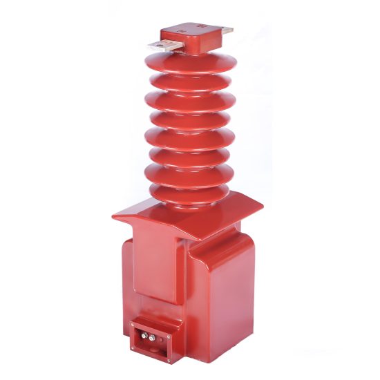
Introduction to the AGE-1026 Current Transformer
The AGE-1026 is a medium-voltage cast-resin current transformer (CT) engineered for precision measurement and dependable protective relay coordination in 33kV power systems. While internationally rated at 33kV per IEC standards, it is functionally compatible with domestic 35kV networks commonly deployed in China and select Asian markets. This dual-voltage compatibility ensures seamless integration across global infrastructure projects without compromising performance or safety margins.
Operating Principle of Cast-Resin Insulation
Cast-resin insulation in the AGE-1026 utilizes vacuum pressure impregnation (VPI) epoxy technology to fully encapsulate the primary conductor, secondary windings, and magnetic core within a homogeneous dielectric matrix. This process eliminates air voids and moisture ingress pathways, significantly enhancing partial discharge resistance—typically below 10 pC at 1.2 × Ur (rated voltage). The epoxy resin exhibits a relative permittivity (εr) of 3.8–4.2 and volume resistivity exceeding 1×10¹⁴ Ω·cm at 20°C. Unlike oil-filled alternatives, the solid dielectric provides intrinsic fire resistance (UL 94 V-0 rated), making it suitable for indoor substations, urban switchgear rooms, and environments with stringent fire codes. Thermal conductivity of the resin (~0.8 W/m·K) enables efficient heat dissipation during overload conditions, supporting continuous operation up to 1.2 × In without degradation.
Advantages Over Oil-Immersed Designs
Compared to traditional oil-immersed CTs, the AGE-1026’s cast-resin construction offers superior environmental resilience. It requires no oil containment systems, eliminating risks of leakage, soil contamination, or maintenance-intensive oil sampling. The absence of flammable fluids reduces fire hazard classification under IEC 61439-2, facilitating installation in confined spaces such as commercial building switchrooms. Mechanical robustness is enhanced through monolithic molding—tested to withstand seismic Zone 3 (0.3g horizontal acceleration per IEC 60068-2-57) and short-circuit electrodynamic forces up to 40 kA for 1 second. Additionally, the compact footprint (typical height: 420 mm, diameter: 210 mm) allows higher equipment density in space-constrained substations. Long-term reliability is further assured by negligible aging of epoxy under thermal cycling (-40°C to +40°C ambient), contrasting with oil’s progressive oxidation and moisture absorption over time.
Typical Application Overview
The AGE-1026 serves dual roles in both revenue-grade metering and high-speed protection schemes. In utility substations, it feeds Class 0.2S or 0.5S secondary windings to AMI (Advanced Metering Infrastructure) systems for accurate energy billing. Simultaneously, its 5P10 or 5P20 protection-class windings interface with numerical relays (e.g., SEL-351, Siemens 7UT6) for overcurrent, earth-fault, and differential protection. Industrial facilities leverage its high accuracy under distorted waveforms (THD ≤ 15%) for motor control centers and arc-furnace monitoring. Renewable integration points—such as solar farm collector feeders—utilize its linear response up to 20 × In to capture fault currents during grid disturbances. Its design accommodates both busbar-through and cable-terminal mounting, supporting retrofit upgrades in legacy 35kV networks without structural modifications.
Technical Specifications
The AGE-1026 adheres to rigorous electrical and mechanical parameters defined by IEC 61869-2 and GB/T 20840.2, ensuring interoperability across global grids.
| Parameter | Value |
|---|---|
| Rated Voltage (Ur) | 33 kV (IEC) / 35 kV (Domestic) |
| System Frequency | 50/60 Hz |
| Primary Current (Ip) | 50–3000 A (standard); up to 4000 A (custom) |
| Secondary Current (Is) | 1 A or 5 A |
| Accuracy Classes | Metering: 0.2S, 0.5S; Protection: 5P10, 5P20, 10P10 |
| Rated Output (Burden) | 2.5–30 VA (metering); 5–50 VA (protection) |
| Insulation Level (LI/AC) | 170 kV / 70 kV (per IEC 60071-1) |
| Short-Time Thermal Current | 40 kA for 1 s (Ith) |
| Dynamic Withstand Current | 100 kA peak (Idyn) |
| Ambient Temperature Range | -40°C to +40°C |
| Altitude Limit | ≤ 1000 m (derating required above) |
| Relative Humidity | ≤ 95% non-condensing |
| Core Material | Grain-Oriented Electrical Steel (GOES), 0.27 mm thickness |
| Partial Discharge | < 10 pC at 1.2 × Ur |
Standard Service Conditions
The AGE-1026 is rated for standard service conditions per IEC 61869-1: ambient temperature range of -40°C to +40°C, relative humidity up to 95% (non-condensing), and installation altitude not exceeding 1000 meters above sea level. At altitudes between 1000–2000 m, the rated voltage must be derated by 1.25% per 100 m increment to maintain dielectric integrity. For coastal or industrial atmospheres with high salt or chemical contamination (pollution degree IV per IEC 60664-1), creepage distance is enhanced to ≥ 25 mm/kV (phase-to-ground), achieved via ribbed shed design on the resin housing. The transformer is designed for continuous operation under unbalanced load conditions with harmonic content up to 15% THD, maintaining accuracy within ±0.2% for metering classes.
Electrical Performance Parameters
Key electrical characteristics include a magnetizing impedance (Zm) exceeding 100 Ω at 5 A secondary current for 5P20 class, ensuring minimal saturation during high-magnitude faults. Composite error at rated accuracy limit factor (ALF) is ≤ 5% for protection windings. For metering windings, phase displacement is limited to ±10 minutes at 100% In for Class 0.2S. The rated symmetrical short-circuit factor (RSSF) is 20, meaning the CT can accurately reproduce primary current up to 20 × In without exceeding composite error limits. Burden tolerance is ±10% of nominal value; exceeding this may shift accuracy class due to increased voltage drop across secondary impedance. Core losses are minimized through GOES lamination with specific loss ≤ 1.0 W/kg at 1.7 T, 50 Hz.
Typical Applications
The AGE-1026’s versatility enables deployment across diverse power system architectures requiring high fidelity current transformation.
Substation Secondary Metering
In transmission and distribution substations, the AGE-1026 provides Class 0.2S or 0.5S secondary outputs to revenue meters compliant with IEC 62053-22. Its low phase error (< ±5 minutes at 20–120% In) ensures accurate reactive energy measurement critical for power factor billing. Installed on 33kV feeder breakers, it interfaces with IEC 61850-9-2 LE sampled value streams in digital substations, where time synchronization (±1 µs) preserves waveform fidelity. The cast-resin body resists tracking from airborne pollutants in urban substations, maintaining insulation resistance > 1000 MΩ after 10 years of service.
Industrial Power Distribution
Heavy industries—including steel mills, petrochemical plants, and data centers—deploy the AGE-1026 on 33kV/35kV switchgear for motor protection and load profiling. Its 5P20 windings drive inverse-time overcurrent relays that coordinate with downstream fuses during motor start-up inrush (6–8 × In for 10–30 seconds). The high dynamic withstand (100 kA peak) protects against arc-flash events in high-fault-current networks. In variable-frequency drive (VFD) environments, the GOES core minimizes hysteresis losses under PWM-induced harmonics, preserving accuracy even with 5th and 7th harmonic dominance.
Renewable Energy Integration
Solar and wind farms utilize the AGE-1026 on collector feeders connecting inverters or turbines to the 33kV grid. During grid faults, its linear response up to 20 × In enables precise fault current injection measurement for compliance with grid codes (e.g., IEEE 1547, ENTSO-E). The transformer’s fast saturation recovery (< 50 ms after DC offset removal) supports adaptive reclosing schemes. Outdoor installations benefit from UV-stabilized resin housing (tested per IEC 60529 IP54) that resists cracking under thermal cycling between desert days (+55°C) and nights (-10°C).
Rural and Suburban Distribution Networks
In rural electrification projects, the AGE-1026’s maintenance-free design reduces operational costs where skilled technicians are scarce. Mounted on pole-top reclosers or pad-mounted switchgear, it provides both metering for tariff collection and protection against tree-contact faults. Its compact size allows installation on existing 35kV poles without structural reinforcement. The 1 A secondary option minimizes copper losses over long cable runs (> 500 m) to remote metering cabinets, improving signal-to-noise ratio for SCADA telemetry.
Urban Underground Networks
For city center ring-main units (RMUs), the AGE-1026’s fire-safe resin meets IEC 60695 glow-wire ignition test requirements (GWIT 850°C). Installed in SF6-insulated switchgear compartments, it operates reliably despite limited ventilation, with surface temperature rise < 55 K above ambient at 1.2 × In. Its immunity to electromagnetic interference (EMI) from nearby traction systems (e.g., metro lines) ensures stable relay operation, validated per IEC 61000-4-3 (10 V/m field strength).
Compliance with International Standards
The AGE-1026 is certified to IEC 61869-2:2012 (Instrument transformers – Part 2: Additional requirements for current transformers) and GB/T 20840.2-2014 (Chinese national equivalent), ensuring global acceptance.
IEC 61869-2 Compliance Details
IEC 61869-2 mandates rigorous type tests including temperature rise (Clause 7.3), short-circuit withstand (Clause 7.5), and accuracy verification under harmonic distortion (Clause 7.8). The AGE-1026 undergoes full-wave lightning impulse testing at 170 kV (positive and negative polarity, 3 shots each) with no flashover or disruptive discharge. Power frequency wet withstand is 70 kV for 1 minute, verified in rain test chambers per IEC 60060-1. Accuracy tests are performed at 5%, 20%, 100%, and 120% of rated current with burdens ranging from 25% to 100% of rated VA. Composite error for 5P20 class must not exceed 5% at 20 × In and rated burden—validated using precision shunts and digital oscilloscopes with 16-bit resolution.
GB/T 20840.2 Alignment and Key Differences
While GB/T 20840.2 closely mirrors IEC 61869-2, key distinctions exist. Chinese standards require an additional 1-minute AC withstand test at 80 kV for 35kV-class equipment (vs. 70 kV in IEC for 33kV). Partial discharge limits are stricter: ≤ 5 pC at 1.2 × Ur for indoor types under GB/T, versus ≤ 10 pC in IEC. Accuracy verification under DC offset (simulating asymmetrical faults) is mandatory in GB/T but optional in IEC. The AGE-1026 meets both by incorporating oversized core cross-sections (≥ 15% margin) and triple-layer secondary winding insulation. Certification is issued by CEPREI (China National Institute of Standardization) alongside IEC CB Scheme reports.
Testing and Certification Requirements
Type testing per IEC 61869-2 includes 12 critical procedures: insulation resistance, dielectric tests, accuracy, temperature rise, short-circuit, radio interference voltage (RIV), partial discharge, mechanical strength, climatic, EMC, fire behavior, and marking durability. Routine tests on every unit comprise insulation resistance (> 5000 MΩ at 2500 V DC), turns ratio (±0.25% tolerance), polarity, and power frequency withstand (70 kV for 1 min). Certificates include test reports from accredited labs (e.g., KEMA, CESI) and declaration of conformity per ISO/IEC 17065.
On-Site Testing Procedures
Post-installation verification ensures the AGE-1026 performs within specifications before energization.
Insulation Resistance Test
Measure insulation resistance between primary-to-secondary, primary-to-ground, and secondary-to-ground using a 2500 V DC megohmmeter. Acceptance criteria: ≥ 1000 MΩ for new units; ≥ 500 MΩ for units in service. Readings below 100 MΩ indicate moisture ingress or resin degradation. Perform at 20–30°C ambient; correct values using temperature coefficient (resistance halves per 10°C rise). Discharge windings for 5 minutes post-test to prevent residual charge hazards.
Turns Ratio Test
Apply low-voltage AC (5–10 V) to secondary winding and measure induced primary voltage. Calculate ratio as Vp/Vs; compare to nameplate (e.g., 600/5 = 120:1). Tolerance: ±0.25% for metering classes, ±0.5% for protection. Use calibrated ratio bridges (e.g., Omicron CT Analyzer) for accuracy. Deviations >1% suggest inter-turn shorts or incorrect tap selection.
Polarity Test
Verify reducing polarity per IEC 61869-2 Figure 3. Connect DC source (+) to P1, (-) to P2. Momentarily close circuit; observe secondary voltage spike on oscilloscope connected to S1 (+), S2 (-). Positive deflection confirms correct polarity. Incorrect polarity causes relay misoperation—e.g., differential protection tripping on load current. Repeat for all secondary windings if multi-ratio.
Power Frequency Withstand Voltage Test
Apply 70 kV RMS at 50 Hz between primary and grounded secondary/core for 1 minute. Use calibrated test transformer with overcurrent trip (≤ 5 mA). No flashover or sustained arcing permitted. For in-service units, perform at 80% of factory test voltage (56 kV). Ensure all secondary terminals are short-circuited and grounded during test to avoid core saturation.
Short-Circuit Test (for CT)
Inject primary current at 100% and 120% In into short-circuited secondary. Measure secondary current with calibrated clamp meter; verify ratio within tolerance. Simultaneously monitor secondary voltage—should remain < 5 V to confirm no open-circuit risk. This validates burden compatibility and detects winding defects. Never leave secondary open during primary energization—risk of lethal overvoltage (> 5 kV).
Preventive Maintenance Guide
Proactive maintenance extends service life beyond 25 years while preventing catastrophic failures.
Periodic Inspection Schedule
Conduct visual inspections quarterly: check for resin cracks, tracking marks, terminal corrosion, or loose hardware. Annually, perform insulation resistance and ratio tests. Every 5 years, execute full dielectric tests (withstand, partial discharge) and accuracy verification under simulated load. In coastal areas, inspect creepage distance annually for salt deposit density (SDD) > 0.1 mg/cm²—clean with deionized water if exceeded. Record all results in asset management systems for trend analysis.
Maintenance Intervals and Fault Diagnosis
| Interval | Tasks | Fault Indicators |
|---|---|---|
| Quarterly | Visual check, IR thermography | Hot spots (>10 K above ambient), discoloration |
| Annually | Insulation resistance, ratio, polarity | Ratio drift >0.5%, IR <500 MΩ |
| 5 Years | Dielectric tests, accuracy validation | PD >20 pC, composite error >6% |
| After Fault | Full suite + core remanence check | Remanence >0.3 T requires degaussing |
Common faults include secondary open-circuit (causing core saturation and overheating), moisture ingress (reducing IR), and mechanical stress fractures from improper handling. Diagnose ratio errors by comparing with sister CTs on same busbar—differences >1% warrant replacement.
Conclusion
The AGE-1026 33kV cast-resin current transformer represents a benchmark in medium-voltage instrumentation, combining IEC 61869-2 and GB/T 20840.2 compliance with robust engineering for demanding utility and industrial environments. Its VPI epoxy resin insulation delivers exceptional dielectric strength, fire safety, and environmental resilience, eliminating the operational liabilities of oil-filled alternatives. Precision-engineered with GOES silicon steel cores, it maintains Class 0.2S metering accuracy and 5P20 protection linearity even under harmonic distortion and high fault currents. Rigorous type testing—including 170 kV lightning impulse and 40 kA short-circuit withstand—validates reliability across global grid conditions. With a design life exceeding 25–30 years under standard service conditions, the AGE-1026 minimizes lifecycle costs through maintenance-free operation and resistance to aging mechanisms like partial discharge and thermal cycling. Its dual-voltage compatibility (33kV IEC / 35kV domestic) ensures seamless deployment in international projects, while compact dimensions facilitate retrofitting in space-constrained substations. For engineers specifying instrumentation for critical infrastructure, the AGE-1026 offers a technically uncompromised solution that aligns with modern grid reliability, safety, and accuracy imperatives.
Frequently Asked Questions (FAQ)
Q1: Can the AGE-1026 be used on a 35kV system rated per Chinese standards?
A: Yes. While labeled 33kV per IEC 61869, the AGE-1026 is tested to 35kV system requirements (80 kV AC withstand per GB/T 20840.2) and is functionally interchangeable in 35kV networks.
Q2: What is the maximum allowable secondary burden for a 5P20 winding?
A: The rated burden (e.g., 15 VA) must not be exceeded. Actual burden = Is² × (Rwire + Rrelay). For 5 A secondary, total loop resistance must be ≤ burden/25 (e.g., 15 VA → ≤ 0.6 Ω).
Q3: Is the AGE-1026 suitable for indoor installation only?
A: No. It is rated for both indoor and outdoor use (IP54 per IEC 60529) with UV-resistant resin. Outdoor installations require proper drainage orientation to prevent water pooling.
Q4: How do I verify polarity during commissioning?
A: Use the DC kick test: apply momentary DC to primary (P1+, P2−); a positive voltage spike on S1 (relative to S2) confirms reducing polarity per IEC 61869-2.
Q5: What happens if the secondary is left open-circuited?
A: Dangerous overvoltages (>5 kV) can develop, risking insulation failure and personnel hazard. Always short-circuit secondary terminals before disconnecting loads.
Q6: Can multiple secondary windings be used simultaneously?
A: Yes, provided total burden per winding does not exceed its rated VA. Cross-coupling effects are negligible due to independent winding isolation.
Q7: What is the minimum order quantity for custom ratios?
A: Standard ratios (e.g., 600/5, 1200/1) are stock items. Custom ratios (e.g., 1800/5) require MOQ of 3 units with 8-week lead time.
Q8: Does the AGE-1026 require periodic oil sampling?
A: No. As a dry-type cast-resin transformer, it contains no liquid insulation and is entirely maintenance-free regarding fluid management.