Article Content
Introduction
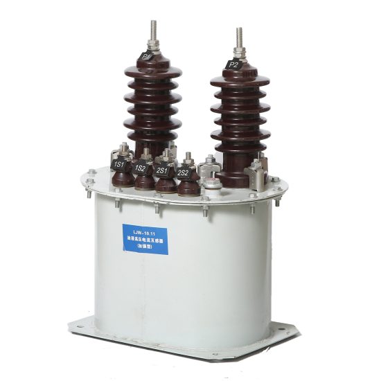
The JWD-10 current transformer is a critical component in medium-voltage power systems, specifically engineered for reliable and accurate current measurement and protection in 10 kV networks. As a resin-insulated, outdoor-type current transformer, the JWD-10 combines robust mechanical construction with high dielectric strength, ensuring long-term performance under demanding environmental conditions. Its primary applications include integration with protective relays, energy meters, and monitoring equipment in substations, industrial plants, and utility distribution systems. By accurately stepping down high primary currents to standardized secondary values (typically 1 A or 5 A), the JWD-10 enables safe interfacing with instrumentation while maintaining galvanic isolation between high-voltage circuits and low-voltage control systems. This guide provides essential selection criteria to ensure optimal performance, safety compliance, and compatibility with existing infrastructure. Proper selection not only enhances measurement fidelity but also safeguards system integrity during fault conditions.
System Voltage
Selecting the appropriate JWD-10 current transformer requires careful consideration of the system voltage to guarantee both operational safety and insulation integrity. The JWD-10 is explicitly rated for 10 kV systems, which refers to the nominal phase-to-phase voltage in three-phase networks. However, it is crucial to understand that the actual operating voltage may vary within permissible limits defined by standards such as IEC 61869 or GB/T 20840. The transformer’s insulation system—including the epoxy resin casting, creepage distance, and dry arcing resistance—must withstand not only continuous operating voltages but also transient overvoltages caused by switching operations or lightning surges.
For 10 kV systems, the highest voltage for equipment (Um) is typically 12 kV. Therefore, the JWD-10 must be tested and certified for this maximum system voltage. Installers should verify that the transformer’s Basic Insulation Level (BIL) meets or exceeds the required impulse withstand voltage, commonly 75 kV for 10 kV class equipment. Additionally, altitude and pollution levels influence insulation performance; at altitudes above 1,000 meters, derating may be necessary due to reduced air density. In heavily polluted or coastal environments, an increased creepage distance (e.g., ≥25 mm/kV) is recommended to prevent flashovers.
| Parameter | Value | Standard Reference |
|---|---|---|
| Nominal System Voltage | 10 kV | IEC 60038 |
| Highest Voltage for Equipment (Um) | 12 kV | IEC 61869-1 |
| Power Frequency Withstand Voltage (1 min) | 28 kV (rms) | GB/T 20840.1 |
| Lightning Impulse Withstand Voltage (BIL) | 75 kV (peak) | IEC 60060-1 |
| Minimum Creepage Distance | 250 mm (standard pollution) | IEC 60815 |
Transformation Ratio
The transformation ratio—defined as the ratio of primary current (Ip) to secondary current (Is)—is a fundamental specification when selecting the JWD-10 current transformer. This ratio determines how the high primary current in the power circuit is scaled down to a manageable level (usually 1 A or 5 A) for connected instruments and relays. Common ratios for the JWD-10 include 50/5, 100/5, 200/5, 400/5, 600/5, and 800/5, though custom ratios like 100/1 or 400/1 are also available for specialized applications requiring lower secondary loading or longer cable runs.
Correct ratio selection hinges on the expected load current and the requirements of downstream devices. For metering applications, the ratio should be chosen so that normal operating current falls within 20% to 100% of the primary rating to ensure accuracy. In protection applications, the ratio must accommodate both normal load and potential fault currents without saturating the core. For instance, if a feeder carries a continuous load of 350 A and may experience short-circuit currents up to 10 kA, a 400/5 ratio would be suitable—it allows accurate metering near full load while providing sufficient headroom for relay operation during faults.
It is also essential to consider whether single-ratio or multi-ratio (tapped secondary) configurations are needed. Multi-ratio CTs offer flexibility by allowing different tap points on the secondary winding (e.g., 400/5 and 200/5 on the same unit), enabling future system upgrades without hardware replacement. However, unused taps must be short-circuited to prevent dangerous open-circuit conditions. Furthermore, the burden imposed by connected devices (expressed in volt-amperes or impedance) must align with the CT’s rated output to avoid ratio errors or saturation.
Finally, note that the JWD-10’s thermal and dynamic current ratings are tied to its transformation ratio. Higher primary ratings generally correlate with greater short-time thermal withstand capability (e.g., 20× rated current for 1 second). Always confirm that the selected ratio supports the system’s prospective fault levels.
| Primary Current (A) | Secondary Current (A) | Common Applications | Notes |
|---|---|---|---|
| 50 | 5 | Small feeders, auxiliary circuits | Limited fault current capacity |
| 100 | 5 or 1 | Metering in light-load circuits | 1 A secondary reduces cable losses |
| 200 | 5 | General distribution feeders | Balanced accuracy and protection |
| 400 | 5 | Main incomers, motor circuits | Suitable for 10 kA fault levels |
| 600 / 800 | 5 | Heavy industrial loads, transformers | Verify thermal rating with system study |
| Multi-ratio (e.g., 400-200/5) | 5 | Future-proof installations | Short unused taps! |
Accuracy Class
Accuracy class defines the permissible error limits of a current transformer under specified operating conditions and is vital for both metering and protection functions. The JWD-10 is available in multiple accuracy classes per international standards (IEC 61869) and Chinese national standards (GB/T 20840), each tailored to distinct applications. For revenue metering, high-precision classes such as 0.2, 0.5, or 0.2S are used, where “S” denotes extended accuracy at low load levels (down to 1% of rated current). Protection applications typically employ classes like 5P10 or 10P15, where the number after “P” indicates the maximum composite error (in percent) at a specified multiple of the rated primary current.
For example, a JWD-10 labeled “0.5/5P10” features dual cores or windings: one optimized for metering (class 0.5, ±0.5% current error and ±0.5° phase error at 100%–120% rated current) and another for protection (class 5P10, ≤5% composite error at 10× rated current). Selecting the correct accuracy class ensures that energy billing remains fair and that protective relays operate reliably during faults without nuisance tripping or failure to trip.
Key considerations include:
- Metering Accuracy: Class 0.2S is preferred for tariff metering due to its performance at 1–120% of rated current. Standard class 0.5 is acceptable for internal monitoring.
- Protection Accuracy: The “P” class must match the relay’s sensitivity and the system’s fault current magnitude. A 5P10 CT guarantees accuracy up to 10× rated current—if the maximum fault current is 6,000 A and the CT ratio is 400/5, the fault multiple is 15×, necessitating at least a 5P15 or 10P20 class.
- Burden Compatibility: Accuracy is guaranteed only when the connected burden does not exceed the CT’s rated burden (e.g., 15 VA for 0.5 class). Excessive burden increases errors and may cause saturation.
Always consult the system protection coordination study and metering requirements before finalizing the accuracy class. Mixing incompatible classes can compromise both safety and financial accountability.
| Accuracy Class | Application | Max Current Error | Phase Displacement Limit | Test Current Range |
|---|---|---|---|---|
| 0.2S | Precision metering (revenue) | ±0.2% | ±10 minutes | 1% – 120% In |
| 0.5 | General metering | ±0.5% | ±30 minutes | 20% – 120% In |
| 5P10 | Overcurrent protection | ≤5% composite error | Not specified | At 10× In |
| 10P15 | Backup protection | ≤10% composite error | Not specified | At 15× In |
5. Burden Calculation
The burden of a current transformer (CT) refers to the total impedance connected to its secondary winding, expressed in volt-amperes (VA) at a specified power factor. Accurate burden calculation is essential to ensure that the CT operates within its accuracy class and does not saturate under normal or fault conditions. The total burden includes the impedance of connected relays, meters, test switches, and the resistance of the wiring between the CT and the devices.
The formula for calculating total burden is:
Ztotal = Zwire + Zrelay + Zcontact + Zmeter
Where:
• Zwire = 2 × ρ × L / A (ρ = resistivity of copper ≈ 0.0178 Ω·mm²/m, L = one-way cable length in meters, A = cross-sectional area in mm²)
• Zrelay, Zmeter = provided by manufacturer (often in VA; convert using Z = VA / I²)
• Zcontact = typically 0.05–0.1 Ω per connection point
| Component | Impedance (Ω) | Notes |
|---|---|---|
| Wiring (2×50 m, 4 mm²) | 0.445 Ω | Z = 2 × 0.0178 × 50 / 4 |
| Protective Relay | 0.200 Ω | Based on 5 VA @ 5 A: Z = 5 / 25 = 0.2 Ω |
| Metering Device | 0.100 Ω | 2.5 VA @ 5 A |
| Test Switch Contacts | 0.100 Ω | Two contacts @ 0.05 Ω each |
| Total Burden | 0.845 Ω | Corresponds to ~21.1 VA @ 5 A |
If the CT is rated for 15 VA, this burden exceeds its rating, risking saturation and inaccurate operation during faults. Therefore, either reduce cable length, increase conductor size, or select a CT with a higher burden rating (e.g., 30 VA). Always verify burden against the CT’s excitation curve to ensure adequate performance margin.
6. Short-Circuit Considerations
Current transformers must withstand high short-circuit currents without mechanical damage or loss of accuracy. During a fault, primary currents can reach 20–100 times the nominal rating, inducing large forces between windings and potentially causing insulation failure or core saturation. Two key parameters govern short-circuit performance: thermal withstand capability and dynamic (electrodynamic) strength.
Thermal Withstand: Expressed as I²t (A²s), it defines the energy the CT can absorb without exceeding temperature limits. For example, a CT rated 20 kA for 1 second has an I²t = (20,000)² × 1 = 400 × 10⁶ A²s.
Dynamic Withstand: The peak current the CT can endure mechanically, typically 2.5 times the RMS short-circuit current (e.g., 50 kA peak for a 20 kA RMS rating).
| Parameter | Requirement | Verification Method |
|---|---|---|
| Primary Short-Circuit Current | 25 kA RMS (3-phase) | From system study |
| CT Thermal Rating | ≥ 25 kA for 1 s | Check nameplate or datasheet |
| CT Dynamic Rating | ≥ 62.5 kA peak | 2.5 × 25 kA |
| Saturation Check | Knee point voltage > Vfault | Vfault = Ifault × Ztotal × N |
For a 1000/5 CT with total burden 0.85 Ω and 25 kA fault current:
Vfault = (25,000 / 1000) × 0.85 × 1000 = 21.25 V
The CT’s knee-point voltage (e.g., 50 V) must exceed this to avoid saturation. If not, consider a higher accuracy class (e.g., 5P20 instead of 5P10) or reduce burden.
7. Environmental Factors
Environmental conditions significantly impact CT performance, longevity, and safety. Key considerations include ambient temperature, humidity, altitude, pollution, and exposure to chemicals or salt spray. CTs installed outdoors or in harsh industrial environments require appropriate enclosures and insulation systems.
Temperature: Standard CTs operate between –25°C and +55°C. Beyond this, derating or special designs (e.g., silicone-filled, stainless steel housings) are needed. High temperatures accelerate insulation aging; low temperatures may embrittle materials.
Altitude: Above 1000 m, air density decreases, reducing dielectric strength. CTs rated for standard altitude may require derating or enhanced creepage distance above 2000 m.
Pollution & Humidity: In coastal or chemical plants, use CTs with IP54 or higher protection, hydrophobic coatings, and increased creepage (e.g., 25 mm/kV for heavy pollution).
| Condition | Impact | Mitigation |
|---|---|---|
| Ambient Temp: –35°C | Brittle epoxy, oil contraction | Low-temp compound, flexible seals |
| Relative Humidity: 95% | Condensation, tracking | Heaters, sealed enclosures, silica gel |
| Coastal Location | Corrosion, salt deposits | Stainless steel hardware, IP66 rating |
| Altitude: 2500 m | Reduced insulation strength | Increase clearance by 20%, use vacuum casting |
Always consult IEC 61869-2 and local standards for environmental classification (e.g., IEC 60721-3). Field inspections should verify no moisture ingress, corrosion, or UV degradation of outdoor units.
8. CT Selection and Installation Checklist
Use this checklist during design, procurement, and commissioning to ensure reliable CT performance:
| # | Check Item | Status (✓/✗) |
|---|---|---|
| 1 | Primary current rating matches system load and fault levels | |
| 2 | Accuracy class suitable for application (e.g., 0.5 for metering, 5P20 for protection) | |
| 3 | Total burden ≤ CT rated burden | |
| 4 | Short-circuit thermal and dynamic ratings exceed system requirements | |
| 5 | Knee-point voltage sufficient to avoid saturation during faults | |
| 6 | Environmental rating (IP, temp, altitude) matches installation site | |
| 7 | Secondary circuits grounded at single point (typically at relay panel) | |
| 8 | No open-circuit condition possible during operation (use shorting test blocks) | |
| 9 | Polarity marked correctly (H1, X1) and verified during commissioning | |
| 10 | Manufacturer’s test certificates and excitation curves available |
Complete this checklist during design review and again during site acceptance testing. Any unchecked item requires corrective action before energization. Proper documentation ensures traceability and supports future maintenance or upgrades.