Article Content
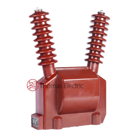
JDZW-35R 33kV Cast-Resin Voltage Transformer for Substation Metering and Protection – IEC 61869-3 Certified
Introduction to the JDZW-35R Voltage Transformer
The JDZW-35R is a single-phase, outdoor-type cast-resin voltage transformer (VT) engineered for precise voltage measurement and reliable protective relay operation in medium-voltage power systems rated at 33kV (IEC standard) or 35kV (domestic Chinese system). Designed in strict compliance with IEC 61869-3 and GB/T 20840.3, this instrument transformer leverages advanced vacuum pressure impregnation (VPI) epoxy resin technology to encapsulate its magnetic core and windings, eliminating the need for flammable insulating oil and significantly enhancing operational safety and environmental resilience.
Unlike traditional oil-immersed VTs, the JDZW-35R’s solid insulation system provides superior resistance to moisture ingress, thermal cycling, and mechanical stress—critical attributes for installations in coastal, industrial, or high-altitude environments. The absence of oil also eliminates risks associated with leakage, fire hazards, and maintenance-intensive oil sampling, making it ideal for urban substations and environmentally sensitive zones.
Typical deployment scenarios include primary and secondary substations, industrial plant switchyards, renewable energy interconnection points (e.g., solar farms and wind parks), and rural distribution feeders where long-term accuracy and minimal maintenance are paramount. With a design life exceeding 25 years under normal operating conditions, the JDZW-35R delivers consistent performance across temperature ranges from –40°C to +40°C and altitudes up to 1,000 meters above sea level.
Operating Principle of Cast-Resin Insulation
The JDZW-35R employs a fully encapsulated VPI epoxy resin system that surrounds both the primary and secondary windings as well as the grain-oriented electrical steel (GOES) core. During manufacturing, the assembled core-winding assembly is placed in a mold and subjected to vacuum to remove air pockets, followed by pressurized injection of thermosetting epoxy resin. This process ensures complete void-free impregnation, resulting in a monolithic, mechanically rigid structure with high dielectric strength (≥70 kV/mm) and excellent tracking resistance (CTI ≥600). The resin’s low coefficient of thermal expansion closely matches that of copper and steel, minimizing internal stresses during thermal transients. This homogeneous insulation system maintains stable capacitance and partial discharge levels below 10 pC at 1.2 × Um/√3, ensuring long-term reliability even under polluted or humid conditions.
Advantages Over Oil-Immersed Designs
Compared to oil-filled VTs, the JDZW-35R offers multiple technical advantages. First, it eliminates fire risk—critical in indoor or densely populated areas—as epoxy resin is self-extinguishing (UL 94 V-0 rated). Second, it requires no periodic oil testing, degassing, or topping-up, reducing lifecycle costs by up to 40% over 25 years. Third, its compact footprint (typically 30–40% smaller than equivalent oil units) simplifies transportation and installation. Additionally, cast-resin VTs exhibit faster response to transient overvoltages due to lower stray capacitance and inductance, improving protection coordination. Environmental compliance is also enhanced: no PCBs, no oil disposal issues, and full recyclability of metallic components at end-of-life. These factors make the JDZW-35R the preferred choice for modern smart grids and green infrastructure projects.
Typical Application Overview
The JDZW-35R is primarily deployed in 33/35kV transmission and distribution networks where accurate voltage transformation is required for revenue metering (Class 0.2 or 0.5) and protective relaying (Class 3P or 6P). In utility substations, it feeds signals to digital multifunction meters, fault recorders, and distance relays. In industrial settings, it supports motor protection schemes and power quality monitoring. For renewable integration, it enables grid-code-compliant synchronization and anti-islanding detection in solar inverters. Its robust outdoor rating (IP54 minimum) allows direct pole or platform mounting without shelter, while optional surge arresters and fuse combinations provide integrated overvoltage protection. The transformer’s dual secondary windings (e.g., 0.2/3P) allow simultaneous connection to metering and protection circuits without cross-interference.
Technical Specifications
The JDZW-35R is engineered to meet stringent electrical and environmental performance criteria. Below is a comprehensive specification table aligned with IEC 61869-3 and GB/T 20840.3:
| Parameter | Value |
|---|---|
| System Voltage (IEC) | 33 kV |
| System Voltage (Domestic) | 35 kV |
| Rated Primary Voltage (Up) | 33,000 / √3 V (phase-to-ground) |
| Rated Secondary Voltage (Us) | 100 / √3 V or 100 V (configurable) |
| Voltage Ratio | 33,000/√3 : 100/√3 V (standard) |
| Accuracy Classes | Metering: 0.2, 0.5; Protection: 3P, 6P |
| Rated Output (per winding) | 30 VA (0.2 class), 50 VA (0.5 class), 100 VA (3P/6P) |
| Insulation Level (LI/AC) | 170 kV / 70 kV (per IEC 60071-1) |
| Short-Time Thermal Withstand | 1 second at 100 A (secondary short-circuit current) |
| Core Material | Grain-Oriented Electrical Steel (GOES), M4 grade |
| Insulation System | VPI Epoxy Resin, Class F (155°C) |
| Ambient Temperature Range | –40°C to +40°C |
| Maximum Altitude | 1,000 m (derating required above) |
| Creepage Distance | ≥25 mm/kV (medium pollution, IV degree) |
| Partial Discharge | <10 pC at 1.2 × Um/√3 |
Standard Service Conditions
The JDZW-35R is rated for continuous operation under standard service conditions defined in IEC 61869-3: ambient temperature between –40°C and +40°C, relative humidity up to 100% (condensing), and installation altitude not exceeding 1,000 meters. At higher altitudes (up to 2,000 m), voltage withstand values must be derated by 1% per 100 m above 1,000 m. The transformer is designed for three-phase systems with effectively grounded neutrals (solidly or low-resistance grounded), though it can operate in isolated-neutral systems with appropriate overvoltage protection. Wind loading up to 150 km/h and seismic activity up to 0.3g (horizontal) are accommodated via reinforced mounting flanges and internal bracing. Humidity resistance is validated through 1,000-hour salt fog and damp heat tests per IEC 60068-2.
Electrical Performance Tolerances
Voltage error and phase displacement must remain within IEC 61869-3 limits under specified burdens and voltages. For a 0.2-class winding at 80–120% of rated voltage and 25–100% of rated burden, voltage error ≤ ±0.2% and phase error ≤ ±10 minutes. For 3P protection class, voltage error ≤ ±3% at 5%–100% of rated voltage and rated burden. Ratio tolerance is ±0.1% for metering classes. Frequency response is flat between 48–52 Hz, with harmonic distortion <0.5% up to the 13th harmonic under linear load. Thermal stability is ensured by limiting temperature rise to ≤60 K for windings (measured by resistance method) at rated output and 1.2 × rated voltage.
Typical Applications
Substation Secondary Metering
In 33/35kV utility substations, the JDZW-35R provides the critical voltage reference for revenue-grade metering systems. Its 0.2-class secondary winding connects directly to static kWh meters or IEC 61850-compliant merging units, ensuring billing accuracy compliant with national regulatory requirements (e.g., China’s DL/T 448). The transformer’s low phase error minimizes reactive energy measurement drift, while its stable ratio over time reduces calibration frequency. Dual-winding configurations allow one output for main metering and another for check metering or SCADA telemetry. Installation typically involves mounting on a support insulator adjacent to circuit breakers, with shielded twisted-pair cables routed to the control house to minimize electromagnetic interference.
Industrial Power Distribution
Large industrial facilities—such as steel mills, chemical plants, and data centers—rely on the JDZW-35R for both power monitoring and motor protection. In these environments, voltage sags, harmonics, and switching transients are common. The cast-resin design’s high mechanical strength and damping characteristics suppress resonant overvoltages that could damage sensitive equipment. Protection-class (3P) outputs feed to multifunction relays (e.g., SEL-751 or Siemens 7SJ) for undervoltage, overvoltage, and loss-of-potential detection. The transformer’s IP54 rating allows outdoor installation near switchgear without enclosures, reducing footprint and cost. Optional thermal sensors embedded in the resin can provide real-time winding temperature data for predictive maintenance.
Renewable Energy Integration
Solar photovoltaic (PV) and wind farms frequently connect to the grid at 35kV, requiring precise voltage sensing for grid synchronization and fault ride-through (FRT) compliance. The JDZW-35R’s fast transient response (<5 ms rise time) ensures inverters detect grid faults within milliseconds, meeting stringent grid codes (e.g., GB/T 19964). Its immunity to DC bias—common in PV systems due to transformerless inverters—prevents core saturation and measurement errors. In microgrid applications, the VT supports islanding detection via rate-of-change-of-frequency (ROCOF) relays. The absence of oil also aligns with sustainability goals of renewable developers, avoiding environmental liabilities during decommissioning.
Rural and Suburban Distribution Networks
In remote or mountainous regions, the JDZW-35R’s maintenance-free operation and resistance to extreme temperatures make it ideal for pole-mounted distribution transformers. It enables remote voltage monitoring via cellular-connected RTUs, supporting voltage optimization and outage management. The high creepage distance (≥825 mm for 33kV) prevents flashovers in coastal or agricultural areas with salt or fertilizer contamination. Utilities often deploy these VTs in automated feeder switching schemes, where accurate voltage signals trigger reclosers during single-phase faults. The lightweight design (typically 80–100 kg) simplifies helicopter or manual installation in inaccessible terrain.
Compliance with International Standards
IEC 61869-3 Certification Details
The JDZW-35R is fully certified to IEC 61869-3:2011 “Instrument transformers – Part 3: Additional requirements for inductive voltage transformers.” This includes rigorous type tests for temperature rise, short-circuit withstand, lightning impulse (1.2/50 µs, 170 kV peak), power frequency withstand (70 kV rms for 1 min), and partial discharge. Accuracy verification is performed across all specified burdens and voltages using calibrated reference standards traceable to national metrology institutes. The standard mandates that protection-class VTs maintain accuracy during transient recovery voltages following fault clearance—a key requirement met by the JDZW-35R’s low leakage inductance and optimized core geometry. Type test reports are available upon request and include oscillograms of impulse and switching surge responses.
Alignment with GB/T 20840.3
GB/T 20840.3-2013 is the Chinese national adoption of IEC 61869-3, with minor modifications reflecting domestic grid practices. Key differences include: (1) nominal system voltage listed as 35kV instead of 33kV, though insulation levels remain identical; (2) mandatory creepage distance of 25 mm/kV for medium pollution (vs. IEC’s recommendation); and (3) additional requirement for thermal stability testing at 1.5 × rated voltage for 30 seconds. The JDZW-35R meets all GB-specific clauses, including the use of domestic GOES materials (e.g., Wuhan Iron & Steel B30P105) and local terminal box dimensions. Certification is issued by authorized Chinese bodies such as CEPREI or SGS China, with factory acceptance tests (FAT) witnessed by grid operators like State Grid or China Southern Power Grid.
Testing and Certification Requirements
Every JDZW-35R unit undergoes routine tests per IEC 61869-3 Clause 12: visual inspection, winding resistance measurement, ratio and polarity verification, power frequency withstand (70 kV for 1 min), and partial discharge (<10 pC at 1.2 × Um/√3). Type tests—conducted on prototype batches—include temperature rise (using mutual heating method), short-circuit current withstand (100 A for 1 s), and dynamic stress tests. Special tests (on request) cover seismic qualification (IEEE 693), electromagnetic compatibility (IEC 61000-4), and accelerated aging (1,000 thermal cycles). Certificates include CE marking for EU markets and CCC for China.
On-Site Testing Procedures
Insulation Resistance Test
Conducted using a 2,500 V DC megohmmeter between primary-to-secondary/ground and secondary-to-ground. Acceptance criterion: ≥10,000 MΩ at 20°C. Correct for temperature using RT = R20 × 2(20–T)/10. Low readings indicate moisture ingress or resin cracking. Perform before and after commissioning to establish baseline.
Turns Ratio Test
Apply 100–200 V AC to primary, measure secondary voltage with calibrated voltmeter. Calculate ratio = Vp/Vs. Tolerance: ±0.1% for metering, ±0.3% for protection. Use automatic ratio testers (e.g., Omicron CT Analyzer) for precision. Deviations >0.5% suggest turn-to-turn shorts or wiring errors.
Polarity Test
Verify reducing polarity per IEC 61869-3 Figure 103. Apply low-voltage DC pulse to primary; observe secondary voltage direction with oscilloscope. Positive-going primary pulse must yield positive-going secondary pulse at marked terminals (H1–X1). Incorrect polarity causes metering reversal and relay misoperation.
Power Frequency Withstand Voltage Test
Apply 70 kV rms, 50 Hz for 1 minute between primary and grounded secondary/core. Leakage current must remain <3 mA. Gradually ramp up/down at 1 kV/s to avoid transient overstress. Failure indicates insulation degradation or voids in resin.
Open-Circuit Characteristic Test
With secondary open, apply 20–120% of rated primary voltage. Record excitation current and secondary voltage. Plot knee-point curve; saturation should occur >1.5 × rated voltage. Excessive magnetizing current (>5% of rated) suggests core lamination damage or poor annealing.
Preventive Maintenance Guide
Periodic Inspection Schedule
Annual visual inspections should check for: (1) surface cracks or UV degradation of resin housing; (2) corrosion on terminals or mounting hardware; (3) loose bolts (torque to 25 N·m); (4) damaged cable glands or moisture in terminal boxes. Clean housing with non-abrasive detergent; avoid solvents that attack epoxy. In coastal areas, inspect every 6 months for salt deposits—clean with deionized water if creepage path conductivity exceeds 20 µS.
Long-Term Maintenance Intervals
| Interval | Action |
|---|---|
| 1 year | Visual inspection, IR scan (hot spots >10 K above ambient warrant investigation) |
| 5 years | Full electrical tests: ratio, polarity, insulation resistance, partial discharge |
| 10 years | Repeat type tests if operating in severe environments (e.g., chemical plants) |
| 25+ years | Evaluate for replacement based on trend analysis of test data |
Record all results in asset management systems. Trending insulation resistance decline >20% over 5 years indicates aging and warrants further diagnostics.
Fault Diagnosis and Troubleshooting
Common failure modes include: (1) Secondary open-circuit during operation—causes core saturation, overheating, and potential resin carbonization. Always short secondary before disconnecting loads. (2) Moisture ingress via cracked housing—detected by rising tan δ (>0.5%) or PD >20 pC. (3) Terminal corrosion—increases contact resistance, leading to localized heating. Use infrared thermography during peak load to identify anomalies. If ratio error exceeds 1%, suspect internal turn faults requiring factory repair.
Conclusion
The JDZW-35R 33kV cast-resin voltage transformer represents a technically mature and field-proven solution for accurate metering and dependable protection in modern medium-voltage networks. By leveraging VPI epoxy resin encapsulation and high-permeability GOES cores, it achieves exceptional dielectric integrity, thermal stability, and mechanical robustness—outperforming legacy oil-immersed designs in safety, environmental impact, and lifecycle cost. Its dual compliance with IEC 61869-3 and GB/T 20840.3 ensures seamless integration into both international and domestic power systems, supporting applications ranging from urban substations to remote renewable sites. Rigorous factory and on-site testing protocols guarantee performance within tight tolerances (±0.1% ratio error, <10 pC partial discharge), while a maintenance-free design enables reliable operation for 25–30 years under standard service conditions. As grids evolve toward digitalization and decarbonization, the JDZW-35R’s compact footprint, immunity to pollution, and compatibility with smart metering infrastructure position it as a cornerstone component for resilient and efficient power delivery. Engineers specifying this VT can confidently expect decades of stable, code-compliant service with minimal intervention.