Article Content
Introduction
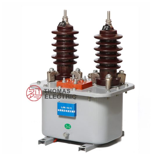
The JDJ-3 voltage transformer is a critical component in medium-voltage power systems, specifically engineered for reliable and accurate voltage measurement and protection at the 12kV level. As an indoor-type, oil-immersed, single-phase electromagnetic voltage transformer, the JDJ-3 ensures stable performance under normal operating conditions while providing electrical isolation between high-voltage circuits and secondary instrumentation or protective relays. Its robust construction meets international standards such as IEC 61869 and GB/T 20840, making it suitable for use in distribution substations, industrial facilities, and commercial power networks. The transformer features primary and secondary windings housed within a sealed tank filled with insulating oil, which serves both as a dielectric medium and a cooling agent. This design enhances safety, minimizes partial discharge, and extends service life even under fluctuating load conditions. Understanding the selection criteria for the JDJ-3 is essential to ensure compatibility with system requirements, regulatory compliance, and long-term operational reliability.
System Voltage
Selecting the appropriate JDJ-3 voltage transformer begins with verifying compatibility with the nominal system voltage. The JDJ-3 is rated for a primary system voltage of 12kV (rms), which corresponds to a maximum system voltage of 12.7kV as per IEC 60038 standard voltage classifications. This rating indicates that the transformer is designed to operate continuously under normal conditions at up to 12kV phase-to-ground or phase-to-phase, depending on the connection scheme. It is crucial to distinguish between system voltage (the nominal operating voltage of the network) and equipment highest voltage (Um), which defines the upper limit for insulation coordination. For the JDJ-3, Um = 12.7kV, ensuring adequate insulation margin against transient overvoltages such as switching surges or lightning impulses.
When integrating the JDJ-3 into a three-phase system, it is typically connected in a V-V or open-delta configuration for metering and protection purposes. In such arrangements, each unit handles a phase-to-ground voltage of approximately 6.93kV (i.e., 12kV/√3). Misapplication—such as using a 12kV-rated transformer on a 15kV or 24kV system—can lead to insulation failure, inaccurate measurements, or catastrophic breakdown. Therefore, engineers must confirm the actual system voltage class before procurement. Additionally, the transformer’s insulation level must align with the system’s basic impulse level (BIL); for 12kV systems, a BIL of 75kV or 95kV is common, and the JDJ-3 is typically tested to withstand these levels.
| Parameter | Value | Standard Reference |
|---|---|---|
| Nominal System Voltage (Un) | 12 kV | IEC 60038 |
| Highest System Voltage (Um) | 12.7 kV | IEC 60071-1 |
| Basic Impulse Level (BIL) | 75 kV or 95 kV | IEC 60060-1 |
| Power Frequency Withstand Voltage (1 min) | 28 kV (rms) | GB/T 20840.3 |
Transformation Ratio
The transformation ratio of a voltage transformer defines the relationship between its primary and secondary voltages and is fundamental to accurate metering and reliable protection functions. For the JDJ-3, the standard transformation ratio is expressed as a primary voltage divided by one or more secondary voltages. Common configurations include single-secondary (e.g., 12,000 V / 100 V) or dual-secondary (e.g., 12,000 V / 100 V / 100/√3 V) outputs, catering to both line-to-line and line-to-neutral measurement needs.
The primary voltage is typically specified as the phase-to-phase system voltage (12kV), while secondary voltages are standardized to facilitate interoperability with meters, relays, and other instrumentation. The most prevalent secondary voltage is 100 V (line-to-line) or 100/√3 ≈ 57.7 V (line-to-neutral), aligning with international practices. It is essential to match the transformation ratio precisely to the system configuration. For instance, in a three-phase four-wire wye-connected system, secondary windings should provide 57.7 V phase-to-neutral to correctly scale down the 6.93 kV phase-to-neutral primary voltage (12kV/√3).
Misalignment in transformation ratios can result in significant measurement errors. A 10% error in voltage scaling, for example, could cause energy billing inaccuracies or improper relay operation during faults. Moreover, the JDJ-3 may offer multiple taps on the primary winding (e.g., ±5%) to accommodate minor system voltage variations, allowing fine-tuning during commissioning. When specifying the ratio, users must declare:
- The nominal primary voltage (e.g., 12 kV)
- The number of secondary windings (1 or 2)
- The secondary voltage(s) per winding (e.g., 100 V, 100/√3 V)
- Intended application for each secondary (metering vs. protection)
Dual-secondary models often dedicate one winding to high-accuracy metering (with lower burden) and another to protection (designed for higher fault current withstand). The total burden connected to each secondary must not exceed the rated output (typically 30 VA, 50 VA, or 100 VA per winding), as excessive loading distorts the voltage waveform and degrades accuracy.
| Primary Voltage (V) | Secondary Configuration | Typical Applications | Rated Output (per winding) |
|---|---|---|---|
| 12,000 | 100 V | Line-to-line metering in delta systems | 30–100 VA |
| 100/√3 V (≈57.7 V) | Line-to-neutral metering in wye systems | 30–100 VA | |
| 12,000 | 100 V / 100/√3 V | Combined metering & protection | 50 VA / 50 VA |
| 12,000 (±5% tap) | 100 V | Systems with voltage regulation needs | 30 VA |
Accuracy Class
Accuracy class is a pivotal specification that defines the permissible error limits in voltage transformation under defined load and frequency conditions. For the JDJ-3 voltage transformer, accuracy classes are assigned separately for metering and protection applications, reflecting their distinct performance requirements. Metering accuracy classes (e.g., 0.2, 0.5, 1.0) indicate the maximum permissible composite error (voltage magnitude and phase angle deviation) at specified burdens and percentages of rated voltage (typically 80–120%). Protection accuracy classes (e.g., 3P or 6P) prioritize performance during fault conditions, ensuring reliable operation of relays even at elevated voltages (up to 190% of rated) and under high burden.
For revenue metering, class 0.2 or 0.5 is commonly required, guaranteeing errors within ±0.2% or ±0.5%, respectively. These tight tolerances are essential for billing integrity. In contrast, class 1.0 or 3.0 may suffice for internal monitoring or non-revenue applications. Protection-class windings, denoted as “3P” (error ≤3% up to 1.9× rated voltage) or “6P” (error ≤6%), are designed to maintain sufficient accuracy during system disturbances when secondary voltage may rise significantly due to neutral displacement or ferroresonance.
The accuracy performance is highly dependent on the connected burden. Each accuracy class is valid only when the actual burden (expressed in volt-amperes, VA) falls within the specified range—usually 25% to 100% of the rated output. Operating below 25% burden can increase phase angle error, while exceeding rated burden causes saturation and magnitude error. Therefore, when selecting a JDJ-3 unit, engineers must specify:
- The required accuracy class for each secondary winding
- The corresponding rated burden (e.g., 30 VA at class 0.5)
- The intended application (metering, protection, or both)
Manufacturers typically provide accuracy curves in test reports, showing error vs. burden and voltage. Compliance with IEC 61869-3 ensures standardized testing methodologies and reliable performance across vendors.
5. Burden Calculation
The burden of a current transformer (CT) refers to the total impedance connected to its secondary winding, expressed in volt-amperes (VA) at a specified power factor. Accurate burden calculation is essential to ensure that the CT operates within its accuracy class and does not saturate under normal or fault conditions. The total burden includes the resistance of connecting leads, the input impedance of protective relays, meters, and any other devices connected to the secondary circuit.
The burden is typically categorized as either rated burden (the maximum VA the CT can supply while maintaining its stated accuracy) or actual burden (the real load presented by the connected devices). Mismatch between these values can lead to measurement errors or protection malfunctions.
| Component | Impedance (Ω) | Power Factor | VA Contribution |
|---|---|---|---|
| Relay Input | 0.05 | 0.8 lagging | 2.5 |
| Connecting Leads (Round Trip) | 0.20 | 1.0 (resistive) | 10.0 |
| Metering Device | 0.03 | 0.9 lagging | 1.5 |
| Total Burden | 0.28 | Composite | 14.0 |
To calculate the total burden in VA:
Burden (VA) = I² × Z × cos(θ),
where I is the secondary current (typically 1 A or 5 A), Z is the total impedance, and cos(θ) is the power factor. For a 5 A system with 0.28 Ω total impedance and an average power factor of 0.85, the burden is approximately 5² × 0.28 × 0.85 ≈ 5.95 VA. However, conservative design often sums individual VA contributions directly, as shown in the table above, yielding a more realistic worst-case estimate.
Exceeding the rated burden causes increased ratio and phase errors, potentially compromising protection coordination. Therefore, CTs must be selected with a rated burden higher than the calculated actual burden, including a safety margin of 10–20%.
6. Short-Circuit Considerations
Current transformers must withstand high short-circuit currents without mechanical damage or loss of insulation integrity. During a fault, primary currents can surge to 20–100 times the nominal rating for durations ranging from 0.1 to 3 seconds. The CT must remain linear enough to provide accurate secondary current for protective relays during this interval.
Two key parameters govern short-circuit performance: short-time thermal rating and dynamic (electrodynamic) strength. The thermal rating defines the maximum RMS current the CT can carry for 1 or 3 seconds without exceeding temperature limits. The dynamic rating addresses mechanical forces between windings due to high peak currents (typically √2 × RMS asymmetrical current).
| Parameter | Symbol | Typical Value | Standard Reference |
|---|---|---|---|
| Short-Time Thermal Current | Ith | 40 kA for 1 s | IEC 61869-2 |
| Dynamic Withstand Current | Idyn | 100 kA peak | IEEE C57.13 |
| X/R Ratio (System) | — | 10–17 | ANSI/IEEE C37.010 |
| Asymmetrical Fault Current | Iasym | ≈ 1.6 × Isym | Depends on X/R |
CT saturation during faults is a critical concern. If the CT core saturates, the secondary current becomes distorted or collapses, leading to relay misoperation (e.g., failure to trip). To mitigate this, engineers use CTs with higher knee-point voltages (Vk) or apply air-cored (linear) CTs in high-fault applications. Additionally, the CT saturation voltage must exceed the voltage developed across the total burden during the fault:
Vrequired = If_sec × (Rct + Rb),
where If_sec is the secondary fault current, Rct is the CT secondary winding resistance, and Rb is the total burden resistance. If Vk > Vrequired, saturation is avoided.
7. Environmental Factors
Environmental conditions significantly influence CT selection, installation, and long-term reliability. Key factors include ambient temperature, humidity, altitude, pollution levels, and exposure to corrosive substances. Standards such as IEC 60068 and IEEE C57.13 define environmental test requirements for instrument transformers.
For outdoor installations, CTs must be housed in weatherproof enclosures (typically IP55 or higher) and constructed with UV-resistant, corrosion-proof materials (e.g., stainless steel flanges, silicone rubber sheds). In coastal or industrial areas, salt fog or chemical exposure necessitates enhanced creepage distances and hydrophobic coatings.
| Condition | Impact on CT | Mitigation Strategy |
|---|---|---|
| High Ambient Temperature (>40°C) | Reduced insulation life, derating required | Select CTs rated for 55°C or 60°C; increase thermal margin |
| High Altitude (>1000 m) | Reduced dielectric strength, cooling efficiency | Apply altitude correction factor per IEC 60071; derate by 1% per 100 m above 1000 m |
| Pollution (Class III/IV) | Flashover risk due to conductive deposits | Increase creepage distance (>25 mm/kV); use RTV silicone coating |
| Humidity & Condensation | Moisture ingress, internal tracking | Hermetic sealing, desiccant breathers, or SF6/oil-filled designs |
Indoor CTs in controlled environments (e.g., switchgear rooms) face fewer challenges but still require compliance with fire safety standards (e.g., IEC 60695 for flammability). In seismic zones, CTs must meet vibration and shock resistance criteria (e.g., IEEE 693). Proper environmental assessment during the design phase prevents premature failure and ensures decades of reliable service.
8. CT Selection and Verification Checklist
Before finalizing CT specifications or commissioning a system, engineers should verify compliance with all technical and operational requirements using the following checklist:
| # | Check Item | Status (✓/✗) | Remarks |
|---|---|---|---|
| 1 | Primary current rating matches system load and fault levels | e.g., 2000/5 A for 1800 A continuous load | |
| 2 | Accuracy class meets application needs (e.g., 5P20 for protection) | Verify knee-point voltage if high burden | |
| 3 | Total burden ≤ CT rated burden (with 15% margin) | Include lead resistance at max operating temp | |
| 4 | Short-circuit withstand (Ith, Idyn) exceeds system fault levels | Confirm X/R ratio and asymmetrical current | |
| 5 | Environmental rating suitable for location (IP, pollution, altitude) | Outdoor? Coastal? High altitude? | |
| 6 | Secondary wiring uses correct gauge and shielding (if required) | Minimize lead resistance; avoid ground loops | |
| 7 | CT polarity marked and verified during installation | Critical for differential and directional schemes |
This checklist should be completed during design review, factory acceptance testing (FAT), and site commissioning. Any unchecked item warrants corrective action before energization. Documentation of verification results ensures traceability and supports future maintenance or upgrades.