Article Content
11kV Cast-Resin Current Transformer ZW-10 for Metering and Protection – IEC 61869-2 Standard
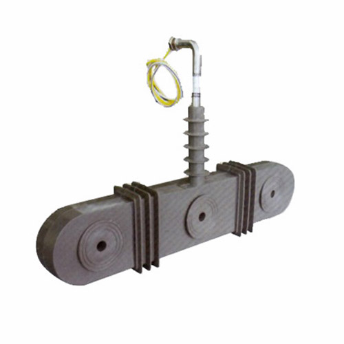
Introduction to the ZW-10 Current Transformer
The ZW-10 is a medium-voltage cast-resin current transformer (CT) engineered for precise current measurement and dependable protective relaying in 11 kV (IEC-rated) power systems, equivalent to domestic 10 kV networks. Designed for both indoor and outdoor deployment, this instrument transformer leverages vacuum pressure impregnation (VPI) epoxy resin technology to encapsulate its magnetic core and windings, ensuring long-term dielectric integrity and mechanical robustness under harsh environmental conditions.
Operating Principle of Cast-Resin Insulation
Cast-resin insulation in the ZW-10 employs a cycloaliphatic epoxy resin system processed under vacuum and pressure to eliminate voids and moisture ingress. This VPI technique fully saturates the primary conductor, secondary windings, and high-permeability grain-oriented electrical steel (GOES) core, forming a monolithic, non-hygroscopic solid structure. Unlike oil-filled alternatives, the resin matrix provides superior tracking resistance (compliant with IEC 60587), eliminates fire hazards, and maintains stable dielectric properties across a wide temperature range (–40°C to +40°C ambient). The absence of liquid insulation also negates maintenance requirements related to oil sampling, leakage, or gas monitoring, significantly reducing lifecycle costs in unattended substations.
Advantages Over Oil-Immersed Designs
Compared to traditional oil-immersed CTs, the ZW-10 offers distinct operational and safety benefits. Its solid insulation eliminates explosion and fire risks, making it suitable for urban substations, underground installations, and facilities with stringent fire codes (e.g., hospitals, data centers). The compact form factor—enabled by higher dielectric strength of epoxy resin (~20 kV/mm vs. ~12 kV/mm for mineral oil)—reduces footprint by up to 30%. Additionally, cast-resin units exhibit negligible aging under partial discharge activity (<5 pC at 1.2 × Um/√3), whereas oil-paper systems degrade progressively due to cellulose breakdown. Environmental compliance is enhanced as the ZW-10 contains no PCBs or hazardous liquids, aligning with RoHS and WEEE directives.
Typical Application Overview
The ZW-10 serves critical roles in utility distribution networks, industrial plants, and renewable energy interconnection points. It interfaces with revenue-class meters (accuracy class 0.2S/0.5S), protective relays (5P10/5P20), and SCADA systems to enable real-time load monitoring, fault detection, and energy billing. Common mounting configurations include busbar-through, cable-through, and support-insulator types, accommodating primary currents from 50 A to 3000 A. Its robust design withstands short-circuit forces up to 25 kA for 1 second, ensuring survivability during grid faults—a key requirement for modern smart grids with high fault-current contributions from distributed generation.
Technical Specifications
The ZW-10 adheres to rigorous electrical and mechanical parameters defined by IEC 61869-2 and GB/T 20840.2, ensuring interoperability across global power systems.
| Parameter | Value |
|---|---|
| Rated Voltage (Ur) | 11 kV (IEC), 10 kV (domestic) |
| System Voltage (Us) | 12 kV (maximum) |
| Primary Current (Ip) | 50–3000 A (standard); custom ratios available |
| Secondary Current (Is) | 1 A or 5 A |
| Accuracy Classes | Metering: 0.2S, 0.5S; Protection: 5P10, 5P20 |
| Rated Output (Burden) | 2.5–30 VA (per IEC 61869-2 Table 102) |
| Insulation Level | Power Frequency Withstand: 28 kV rms / 1 min Lightning Impulse: 75 kV peak (1.2/50 μs) |
| Short-Time Thermal Current | 25 kA for 1 s (I²t = 625 kA²s) |
| Dynamic Withstand Current | 62.5 kA peak (2.5 × thermal current) |
| Ambient Temperature Range | –40°C to +40°C |
| Altitude Limit | ≤1000 m (derating required above 1000 m per IEC 60071-2) |
| Relative Humidity | Up to 95% non-condensing |
| Core Material | Grain-Oriented Electrical Steel (GOES), 0.27 mm thickness |
| Insulation System | Vacuum Pressure Impregnated (VPI) cycloaliphatic epoxy resin |
Standard Service Conditions
The ZW-10 is rated for continuous operation under standard service conditions per IEC 61869-1 Clause 5. Ambient temperature extremes of –40°C to +40°C are accommodated without derating, though secondary burden accuracy may vary slightly outside 15–30°C. At altitudes exceeding 1000 m, the power frequency withstand voltage must be reduced by 1% per 100 m above sea level; for example, at 2000 m, the test voltage becomes 25.2 kV rms. Relative humidity up to 95% is permissible provided condensation does not occur—achieved through hydrophobic resin formulation and sealed terminal boxes (IP54 ingress protection). These conditions ensure reliable performance in diverse climates, from arid deserts to humid coastal regions.
Electrical Performance Tolerances
Current error and phase displacement comply strictly with IEC 61869-2 Table 104. For a 0.2S class unit at 100% rated current and 25% rated burden, current error must not exceed ±0.2%, and phase displacement ≤±10 minutes. Protection-class CTs (5P20) maintain composite error ≤5% at 20× rated current with rated burden. Burden tolerance is ±10% of declared value. Ratio error is verified during factory testing using calibrated reference standards traceable to national metrology institutes (e.g., NIST, PTB), with acceptance criteria of ±0.1% for metering classes. These tight tolerances ensure compatibility with modern digital relays requiring high-fidelity waveform reproduction during transient events.
Typical Applications
The ZW-10’s versatility makes it indispensable across multiple segments of the power delivery chain.
Substation Secondary Metering
In 11 kV primary substations, the ZW-10 feeds revenue-grade meters for accurate energy billing between utilities and large consumers. Installed on outgoing feeders, it typically operates at 0.2S accuracy class with 5 A secondary output connected to kWh meters via shielded twisted-pair cables (min. 2.5 mm² cross-section). To minimize errors, the total loop impedance—including meter input, wiring resistance, and contact resistance—must not exceed the CT’s rated burden (e.g., 10 VA at 5 A = 0.4 Ω max). This application demands low remanence cores to prevent saturation during motor starting inrush, which could distort metering during subsequent normal operation.
Industrial Power Distribution
Within manufacturing facilities, the ZW-10 monitors feeder loads and enables selective coordination of circuit breakers. Protection-class variants (5P10) supply inputs to overcurrent relays (e.g., IEC 60255-compliant devices) set to trip at 1.5–2× full-load current. The CT’s high knee-point voltage (>150 V for 5P20 at 20× Ip) ensures linear response during bolted faults, preventing relay misoperation. In arc-flash mitigation schemes, fast-acting relays use ZW-10 signals to clear faults within 3–5 cycles, limiting incident energy exposure for personnel.
Renewable Energy Integration
Solar farms and wind parks utilize the ZW-10 at the point of common coupling (PCC) to 11 kV distribution feeders. Here, it supports anti-islanding protection, power quality monitoring (THD, harmonics), and export/import metering. Due to variable generation profiles, the CT must maintain accuracy down to 1% of rated current—fulfilled by 0.5S class models with extended linear ranges. The cast-resin housing resists UV degradation and thermal cycling from diurnal temperature swings, critical for desert or offshore installations.
Rural and Suburban Distribution Networks
In overhead line applications, pole-mounted ZW-10 units provide fault detection for sectionalizers and reclosers. Their lightweight design (typically 12–18 kg) simplifies installation on wooden poles, while hydrophobic sheds prevent flashovers during fog or light rain. For rural electrification projects, cost-effective 5P10 models enable basic overcurrent protection without requiring auxiliary power supplies—leveraging self-powered relays that operate directly from CT secondary current.
Urban Underground Networks
Compact gas-insulated switchgear (GIS) and ring main units (RMUs) in cities integrate ZW-10 CTs for space-constrained metering and protection. The absence of oil eliminates contamination risks in confined vaults, and the IP54-rated terminal box prevents ingress from high-pressure water jets during cleaning. In smart city deployments, digital outputs (via merging units per IEC 61850-9-2 LE) can be retrofitted using analog-to-digital converters connected to the secondary terminals.
Compliance with International Standards
The ZW-10 is certified to IEC 61869-2:2012 (“Instrument transformers – Part 2: Additional requirements for current transformers”) and harmonized Chinese standard GB/T 20840.2-2014, ensuring global acceptance.
IEC 61869-2 Certification Details
Compliance encompasses type tests, routine tests, and special tests per IEC 61869-2 Clauses 7–9. Type tests include temperature rise (ΔT ≤ 60 K for windings), short-circuit withstand (25 kA/1 s), and impulse voltage (75 kV peak). Routine tests performed on every unit comprise power frequency withstand (28 kV/1 min), partial discharge (<10 pC at 1.2 × Ur/√3), and accuracy verification. Special tests—such as seismic withstand (optional per IEC 60068-2-57) or chopped impulse—are available upon request. Certification is issued by accredited bodies like KEMA, CESI, or TÜV SÜD, with test reports valid for five years.
Alignment with GB/T 20840.2
GB/T 20840.2 mirrors IEC 61869-2 but includes supplementary requirements for the Chinese market. Key additions involve stricter pollution degree classification (III instead of II for outdoor units) and mandatory salt fog testing (1000 hours per IEC 60068-2-11) for coastal regions. Domestic 10 kV system compatibility is addressed by allowing Ur = 10 kV labeling alongside IEC 11 kV, though electrical parameters remain identical. Chinese grid codes (e.g., State Grid Q/GDW 13001) further mandate 5-minute thermal withstand capability for certain applications—a feature optionally available in the ZW-10 series.
Differences Between IEC and Domestic Standards
While IEC 61869-2 permits secondary currents of 1 A or 5 A globally, GB/T 20840.2 historically favored 5 A in China—though 1 A adoption is increasing for new smart grid projects to reduce copper losses. Accuracy class notation is consistent (e.g., 0.2S), but GB standards require additional verification at 20% and 120% of rated current, whereas IEC focuses on 100% and 120%. Insulation coordination also differs slightly: GB specifies a lightning impulse level of 75 kV for 10 kV systems, matching IEC’s 11 kV requirement, thus enabling dual-labeling without design changes.
On-Site Testing Procedures
Field commissioning requires verification of insulation integrity, ratio accuracy, and polarity to ensure safe grid integration.
Insulation Resistance Test
Using a 2500 V DC megohmmeter, measure insulation resistance between primary-to-secondary, primary-to-ground, and secondary-to-ground. Acceptance criteria per IEC 60270: minimum 1000 MΩ at 20°C. Values below 500 MΩ indicate moisture ingress or resin cracking and warrant further investigation via tan delta or partial discharge testing. Temperature correction is applied using R₂₀ = Rₜ × 1.5(t–20)/10, where t is ambient temperature in °C.
Turns Ratio Test
Apply a low-voltage AC source (50–100 V) to the primary and measure secondary voltage. Calculate actual ratio as Vp/Vs; compare to nameplate ratio. Tolerance per IEC 61869-2: ±0.5% for protection CTs, ±0.25% for metering CTs. Modern ratio testers (e.g., Omicron CT Analyzer) automate this with <0.05% measurement uncertainty. Deviations >1% suggest winding shorts or incorrect tap selection.
Polarity Test
Verify reducing polarity using the DC kick method: connect a 6–12 V battery momentarily across primary terminals (P1 to P2). Observe secondary voltage deflection on a center-zero galvanometer connected to S1–S2. A positive kick confirms correct polarity (S1 corresponds to P1). Incorrect polarity causes 180° phase shift, leading to relay miscoordination or negative meter readings. Digital multimeters with min/max hold can substitute for galvanometers.
Power Frequency Withstand Voltage Test
Apply 28 kV rms at 50 Hz between primary and grounded secondary/enclosure for 1 minute. Use a calibrated test transformer with overcurrent trip (≤100 mA). No flashover or disruptive discharge constitutes pass. For refurbished units, apply 80% of factory test voltage (22.4 kV). This test validates dielectric strength after transport-induced microcracks.
Short-Circuit Test (for CTs)
Unlike VTs, CTs require secondary short-circuit verification. Short S1–S2 and inject 10–20% of rated primary current. Measure secondary current; deviation from expected value should be within accuracy class limits. Open-circuiting a live CT induces dangerous overvoltages (>3 kV)—this test confirms secondary integrity before energization. Always use shorting links during maintenance.
Preventive Maintenance Guide
Proactive maintenance extends service life beyond 25 years and prevents unexpected failures.
Periodic Inspection Schedule
Annual visual inspections check for resin cracks, terminal corrosion, and mounting hardware integrity. Clean sheds with deionized water if pollution accumulation exceeds 0.1 mg/cm² (measured via ESDD/NSDD). Every five years, perform electrical tests: insulation resistance, ratio, and polarity. In high-pollution areas (industrial/coastal), increase frequency to biannual. Thermographic scans during peak load detect abnormal heating at connections (>10 K above ambient warrants tightening).
Maintenance Intervals and Fault Diagnosis
| Interval | Tasks | Fault Indicators |
|---|---|---|
| Annual | Visual inspection, terminal torque check (12 N·m for M6 bolts), IR scan | Discoloration, tracking marks, loose hardware |
| 5-Year | Insulation resistance, ratio test, polarity verification | Ratio error >1%, IR <500 MΩ |
| 10-Year | Partial discharge measurement (<20 pC acceptable) | PD >50 pC indicates internal voids |
Common failure modes include secondary open-circuit (causing core saturation and overheating) and moisture ingress through degraded gaskets. If accuracy drifts suddenly, inspect for broken secondary strands or corroded terminals increasing burden beyond rating.
Conclusion
The ZW-10 11kV cast-resin current transformer represents a benchmark in medium-voltage instrumentation, combining precision metrology with rugged reliability for critical grid applications. Its VPI epoxy resin encapsulation eliminates fire hazards and maintenance burdens associated with oil-filled designs, while the GOES core ensures low losses and high accuracy across metering (0.2S) and protection (5P20) classes. Full compliance with IEC 61869-2 and GB/T 20840.2 guarantees interoperability in international and domestic 10/11 kV systems, supported by rigorous type testing for short-circuit withstand (25 kA/1 s) and dielectric strength (28 kV/75 kV). Field-proven in environments ranging from arid deserts to humid coastal zones, the ZW-10 delivers exceptional longevity—typically exceeding 25 to 30 years—with minimal preventive maintenance. Its compact, environmentally inert construction makes it ideal for space-constrained urban substations, renewable integration points, and industrial facilities demanding fail-safe protection and revenue-grade metering. As power systems evolve toward digitalization and distributed generation, the ZW-10’s robust analog foundation remains essential for accurate sensing, reliable fault clearing, and regulatory compliance across the global energy infrastructure.