Article Content
Introduction to the CT-10K Current Transformer
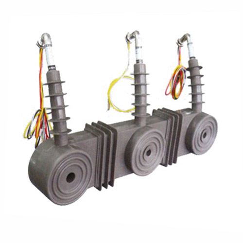
The CT-10K is a high-reliability, cast-resin insulated current transformer (CT) engineered for accurate current measurement and protective relay operation in medium-voltage power systems rated at 11kV (IEC standard), equivalent to 10kV in domestic applications. Designed in strict accordance with IEC 61869-2 and GB/T 20840.2, this device leverages advanced vacuum pressure impregnation (VPI) epoxy resin technology to encapsulate its magnetic core and windings, ensuring long-term dielectric integrity and mechanical robustness.
Operating Principle of Cast-Resin Insulation
Cast-resin insulation in the CT-10K employs a cycloaliphatic epoxy resin system cured under vacuum and pressure to eliminate voids and moisture ingress. This process fully encapsulates the primary conductor, secondary windings, and GOES (grain-oriented electrical steel) core into a monolithic solid block. The resulting structure provides excellent tracking resistance (CTI > 600 V), high thermal conductivity (~0.8 W/m·K), and superior resistance to partial discharge—typically <5 pC at 1.2 × Um/√3 (7.6 kV). Unlike oil-filled alternatives, the solid dielectric eliminates fire hazards, environmental contamination risks, and maintenance-intensive oil sampling protocols.
Advantages Over Oil-Immersed Designs
Compared to traditional oil-immersed CTs, the CT-10K offers significant operational benefits. Its dry-type construction eliminates the need for conservators, breathers, or oil-level monitoring, reducing lifecycle costs by up to 30%. The absence of flammable fluids makes it suitable for indoor substations, urban switchgear rooms, and environmentally sensitive zones. Additionally, the cast-resin body exhibits minimal aging under thermal cycling (–40°C to +40°C ambient), with no degradation in dielectric strength over decades of service. Mechanical stability is enhanced through integral flanges and mounting brackets molded directly into the resin housing, preventing misalignment during seismic events (tested per IEC 60068-2-6).
Typical Applications Overview
The CT-10K is deployed across utility substations, industrial plants, and renewable energy interconnection points where precision, safety, and longevity are critical. It supports both metering (accuracy classes 0.2S/0.5S) and protection (5P10/5P20) functions within the same unit via dual secondary windings. Common installations include ring main units (RMUs), metal-clad switchgear, and overhead line reclosers operating at 11kV nominal system voltage. Its compact footprint (typically 220 mm height × 150 mm diameter) enables retrofitting into legacy infrastructure without major civil modifications.
Technical Specifications
The CT-10K delivers precise performance across a defined set of electrical and environmental parameters, ensuring interoperability with modern protection relays and revenue-grade metering systems.
Electrical Ratings and Performance Parameters
Rated primary voltage: 11kV (Um = 12kV); domestic equivalent: 10kV. Standard current ratios include 50/1A, 100/1A, 200/5A, 400/5A, and 600/1A, with custom ratios available upon request. Accuracy classes comply with IEC 61869-2: Class 0.2S (±0.2% error at 20–120% In) for metering; Class 5P10 (composite error ≤5% at 10×In) for protection. Rated burden: 5–30 VA per secondary winding. Short-time thermal current rating: 20 kA for 1 second (Ith²t = 400 kA²s). Dynamic withstand current: 50 kA peak. Insulation level: Power frequency withstand voltage = 28 kV rms for 1 minute; lightning impulse withstand = 75 kV peak (1.2/50 μs waveform).
Environmental and Mechanical Specifications
The CT-10K operates reliably under standard service conditions per IEC 60060-1: ambient temperature range –40°C to +40°C, relative humidity ≤95% non-condensing, and altitude ≤1000 m above sea level (derating required above 1000 m). The housing is UV-stabilized for outdoor use (IP54 rating when mounted vertically), with optional IP55 for coastal or dusty environments. Creepage distance: ≥25 mm/kV (minimum 275 mm for 11kV), satisfying pollution degree III requirements. Weight: approximately 8–12 kg depending on ratio and core configuration. Terminal blocks accept 2.5–6 mm² stranded copper conductors with screw-type clamping.
Core and Winding Construction Details
The magnetic circuit utilizes high-permeability GOES silicon steel laminations (grade M4 or equivalent, thickness 0.23–0.27 mm), annealed to minimize hysteresis loss. Secondary windings are wound with enameled copper wire (Class F insulation, 155°C rating) and embedded in the resin matrix to prevent movement-induced microphonics. Primary conductor is either a solid copper bar (for through-type designs) or a toroidal window accommodating busbars up to 60×10 mm cross-section. All internal connections are ultrasonically welded to eliminate solder joint failures under thermal stress.
Typical Applications
The CT-10K serves diverse roles in modern power infrastructure, combining metrological accuracy with rugged reliability.
Substation Secondary Metering Systems
In 11kV distribution substations, the CT-10K’s 0.2S-class secondary winding interfaces with digital energy meters (e.g., IEC 62053-22 compliant) to enable accurate billing and load profiling. Its low phase displacement (<10 minutes at 100% In) ensures compliance with revenue metering regulations. For example, a municipal utility in Southeast Asia uses CT-10K units (400/5A, 0.2S/5P20) across 120+ pad-mounted transformers, achieving ±0.3% billing accuracy over five years without recalibration.
Industrial Power Distribution Protection
Within manufacturing facilities, the CT-10K feeds protection-class windings (5P20) to numerical relays (e.g., SEL-751, Siemens 7SJ62) for feeder overcurrent, earth fault, and motor stall detection. Its high saturation point (Vk ≥ 200 V at 1 A secondary) prevents maloperation during motor inrush or transformer energization transients. A steel mill in Germany retrofitted aging oil-CTs with CT-10K units on 11kV arc furnace feeders, eliminating nuisance tripping caused by core remanence in older designs.
Renewable Energy Integration Points
At solar PV and wind farm grid interconnection points, the CT-10K monitors bidirectional power flow and provides fault current data for anti-islanding protection. Its linear response down to 1% of rated current supports low-load efficiency tracking. In a 20 MW solar plant in Spain, CT-10K (600/1A, 0.5S/5P10) units enabled precise reactive power control per ENTSO-E grid codes, maintaining voltage within ±2% tolerance during cloud-induced irradiance swings.
Rural and Suburban Distribution Networks
For rural electrification projects, the CT-10K’s maintenance-free design reduces operational expenditure in remote areas. Mounted on pole-top reclosers or underground RMUs, it withstands wide temperature swings and humidity without performance drift. A utility in India deployed 500+ CT-10K units across 10kV feeders, reporting zero failures over eight years despite monsoon exposure and dust accumulation—attributed to the hydrophobic resin surface and sealed terminal box.
Compliance with International Standards
The CT-10K meets stringent global and regional standards, ensuring interoperability and regulatory acceptance.
IEC 61869-2 Certification Requirements
IEC 61869-2 governs the design, testing, and marking of instrument transformers for AC systems >1 kV. The CT-10K complies with all mandatory clauses: accuracy verification per Annex B (ratio and phase error tests at 5%, 20%, 100%, and 120% In); temperature rise limits (<60 K for windings); short-circuit withstand per Clause 12; and partial discharge levels (<10 pC at 1.2 × Um/√3). Type tests were performed at an ISO/IEC 17025-accredited lab, with routine tests conducted on every unit before shipment.
Alignment with GB/T 20840.2
GB/T 20840.2 is China’s national adoption of IEC 61869-2, with minor deviations in labeling and test documentation. The CT-10K satisfies all technical provisions, including the requirement for dual marking (11kV IEC / 10kV GB) and Chinese-language terminal diagrams. Key differences include stricter creepage distance rules in GB (≥31 mm/kV vs. IEC’s 25 mm/kV for PD III), which the CT-10K exceeds with 300 mm total creepage.
Testing and Certification Documentation
Each CT-10K ships with a test report detailing: insulation resistance (>1000 MΩ at 2500 V DC), turns ratio error (within ±0.1% of nominal), polarity verification (reducing polarity confirmed), and power frequency withstand (28 kV for 60 s, no flashover). Certificates include IECEx for hazardous areas (optional), CE marking per EMC Directive 2014/30/EU, and CQC certification for Chinese markets.
On-Site Testing Procedures
Field commissioning requires rigorous validation of electrical integrity and performance.
Insulation Resistance Test
Perform using a 2500 V DC megohmmeter between primary-to-secondary, primary-to-ground, and secondary-to-ground. Acceptance criterion: ≥1000 MΩ at 20°C. Correct for temperature using R₂₀ = Rₜ × 1.5^(t–20)/10. Low readings indicate moisture ingress or resin cracking—investigate immediately. Always discharge the CT after testing (short secondary terminals and ground).
Turns Ratio Verification
Use a dedicated CT analyzer (e.g., Omicron CT Analyzer) applying 1–5 V AC to the secondary while measuring primary induced voltage. Calculate ratio as V_primary / V_secondary. Tolerance: ±0.1% of nameplate value for metering class; ±0.5% for protection class. Example: For 400/5A CT, measured ratio must be 79.6–80.4:1. Deviations suggest winding shorts or incorrect tap selection.
Polarity Confirmation
Verify reducing polarity using the DC kick method: momentarily apply 6–12 V DC to P1–P2; observe secondary voltage spike direction on an oscilloscope or analog voltmeter. Positive deflection at S1 confirms correct polarity. Incorrect polarity causes wattmeter reversal and relay miscoordination—critical in differential protection schemes.
Power Frequency Withstand Voltage Test
Apply 28 kV rms (50 Hz) for 60 seconds between primary and grounded secondary/housing. Use a calibrated HV test set with overcurrent trip (≤100 mA). No flashover or sustained arcing permitted. Pre-test: ensure secondary windings are short-circuited and grounded to prevent dangerous overvoltages from capacitive coupling.
Short-Circuit Characteristic Test
Inject 10–20× rated secondary current (e.g., 50 A for 5 A secondary) to verify knee-point voltage (Vk) and excitation curve per IEC 61869-2 Annex D. For 5P20 CTs, Vk must exceed 200 V at 1 A secondary to ensure adequate saturation margin during faults. Plot I_excitation vs. V_secondary; nonlinearity onset defines Vk. Low Vk indicates core damage or incorrect material grade.
Preventive Maintenance Guide
Proactive maintenance extends service life and prevents unexpected outages.
Annual Visual and Electrical Inspection
Inspect housing for cracks, UV degradation, or tracking marks. Clean surface with isopropyl alcohol if contaminated. Check terminal tightness (torque: 2.0 N·m for M6 screws). Measure insulation resistance annually—decline >20% from baseline warrants further investigation. Verify secondary wiring continuity and grounding integrity (resistance <0.1 Ω).
Five-Year Comprehensive Maintenance Schedule
Every 60 months, perform full re-commissioning tests: ratio, polarity, insulation resistance, and excitation curve. Compare results to factory baseline; significant shifts (>5% in Vk or >10% in insulation resistance) indicate internal deterioration. Replace gaskets on terminal boxes if hardened. For outdoor units, inspect mounting hardware for corrosion—apply zinc-rich paint if needed.
Maintenance Intervals and Fault Diagnosis Table
| Interval | Task | Fault Indicator | Corrective Action |
|---|---|---|---|
| Annually | Visual inspection, IR test | IR <500 MΩ | Dry out or replace |
| 5 Years | Full electrical tests | Vk drop >10% | Core replacement |
| After Fault | Post-fault diagnostics | Ratio error >1% | Winding repair |
Common failure modes include secondary open-circuit during operation (causing core saturation and insulation puncture) and moisture ingress through cracked resin—both preventable with proper handling and sealing.
Conclusion
The CT-10K 11kV cast-resin current transformer represents a benchmark in medium-voltage instrumentation, combining IEC 61869-2 compliance with field-proven reliability. Its VPI epoxy resin encapsulation eliminates the fire and environmental risks associated with oil-filled alternatives, while the GOES silicon steel core ensures metrological precision across metering and protection applications. With a design life exceeding 25–30 years under standard service conditions, the CT-10K minimizes total cost of ownership through zero-maintenance operation and resilience to harsh environments—from desert heat to tropical humidity. Utilities and industrial operators benefit from consistent performance metrics: ratio errors within ±0.1%, phase displacement below 10 minutes, and dielectric strength maintained over decades. As power systems evolve toward smarter, more distributed architectures, the CT-10K’s compatibility with digital relays and revenue meters ensures seamless integration into next-generation grid infrastructure. Its adherence to both international (IEC) and domestic (GB) standards further guarantees regulatory acceptance across global markets, making it a versatile choice for new installations and legacy upgrades alike.
Frequently Asked Questions (FAQ)
Q1: Can the CT-10K be used on a 10kV domestic system even though it’s rated 11kV?
Yes. The 11kV rating (Um = 12kV) aligns with IEC system voltage definitions, while 10kV is the nominal operating voltage in many countries (e.g., China, India). The CT-10K is explicitly designed for this dual-marking scenario per GB/T 20840.2.
Q2: What happens if the secondary winding is left open during operation?
An open secondary induces dangerously high voltages (several kV) due to unopposed magnetizing current, risking insulation breakdown and personnel hazard. Always short-circuit secondary terminals before disconnecting loads.
Q3: How often should insulation resistance be tested?
Annually under normal conditions. Increase to quarterly in high-humidity or polluted environments (e.g., coastal, industrial zones).
Q4: Is the CT-10K suitable for indoor GIS applications?
Yes, provided ambient temperature remains within –5°C to +40°C. Its compact size and zero-emission profile make it ideal for gas-insulated switchgear bays.
Q5: What is the maximum allowable burden for a 0.2S class winding?
Typically 10–15 VA for 1 A secondaries; 15–30 VA for 5 A secondaries. Exceeding burden degrades accuracy—always verify with connected meter impedance.
Q6: Can multiple CT-10K units share a common ground point?
Yes, but each secondary winding must be individually grounded at one point only (usually at the relay panel) to avoid circulating currents. Never ground at both CT and relay ends.