Article Content
11kV Cast-Resin Voltage Transformer JDZW-35R for Metering and Protection – IEC 61869-3 Standard
Introduction to the JDZW-35R Voltage Transformer
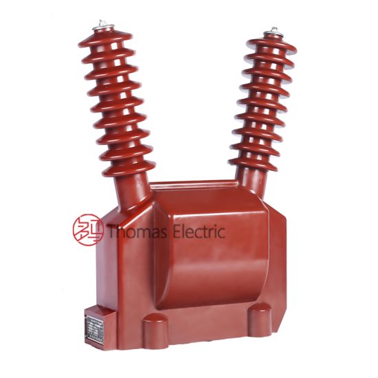
The JDZW-35R is a single-phase, outdoor-rated cast-resin voltage transformer (VT) designed for accurate voltage measurement and reliable protective relay operation in medium-voltage power systems operating at 11kV (IEC standard) or 10kV (domestic Chinese system). As a critical component in substation secondary circuits, it provides galvanically isolated, scaled-down voltage signals proportional to the primary system voltage, enabling safe interfacing with metering instruments, protective relays, and monitoring equipment.
Operating Principle of Cast-Resin Insulation
Cast-resin insulation in the JDZW-35R employs vacuum pressure impregnation (VPI) technology using cycloaliphatic epoxy resin systems. The primary and secondary windings—wound on grain-oriented electrical steel (GOES) cores—are fully encapsulated under vacuum to eliminate air voids and moisture ingress. This monolithic structure provides superior dielectric strength, tracking resistance, and mechanical stability compared to traditional oil-paper or air-insulated designs. The resin’s high glass transition temperature (>110°C) ensures dimensional stability under thermal cycling, while its hydrophobic surface minimizes pollution-induced flashovers in coastal or industrial environments. Partial discharge levels are maintained below 10 pC at 1.2 × Um/√3 (7.6 kV), as required by IEC 61869-3.
Advantages Over Oil-Immersed Designs
Unlike oil-filled VTs, the JDZW-35R eliminates fire hazards, environmental contamination risks, and maintenance-intensive oil sampling. Its dry-type construction offers faster commissioning (no oil filling or degassing), reduced weight (~85 kg vs. ~150 kg for equivalent oil units), and immunity to oil degradation over time. The absence of conservators, breathers, or oil-level indicators simplifies installation and reduces lifecycle costs. Additionally, cast-resin VTs exhibit lower thermal time constants, enabling quicker response to transient overvoltages without thermal runaway. These attributes make the JDZW-35R particularly suitable for indoor substations, urban switchgear rooms, and renewable energy sites where safety and space constraints are paramount.
Typical Applications Overview
The JDZW-35R is engineered for continuous operation in 11kV/10kV distribution networks, supporting both revenue metering (accuracy class 0.2 or 0.5) and protection functions (accuracy class 3P or 6P). It is commonly deployed in ring main units (RMUs), pad-mounted substations, and overhead line sectionalizing points. Its robust design withstands switching surges up to 75 kV (BIL) and temporary overvoltages of 1.9 × Un for 8 hours, ensuring reliability during fault conditions. With an expected service life exceeding 25 years under standard operating conditions, it represents a long-term asset for utilities and industrial operators seeking low-maintenance, high-accuracy voltage transformation.
Technical Specifications
The JDZW-35R adheres strictly to the electrical and mechanical parameters defined in IEC 61869-3 and GB/T 20840.3, ensuring interoperability across global and domestic grids.
Rated Electrical Parameters
Key electrical ratings include a primary voltage of 11/√3 kV (phase-to-earth) for 11kV systems or 10/√3 kV for 10kV networks. Standard secondary voltages are 100/√3 V or 110/√3 V, with dual or triple secondary windings available for combined metering and protection outputs. Accuracy classes comply with IEC 61869-3: Class 0.2 (±0.2% ratio error, ±10′ phase displacement) for metering; Class 3P (±3% error at 5%–100% rated voltage) for protection. Rated burdens range from 10 VA to 100 VA per winding. The insulation level is Um = 12 kV, with power frequency withstand voltage of 28 kV (rms, 1 min) and lightning impulse withstand voltage of 75 kV (peak, 1.2/50 µs). Thermal short-time current rating is 0.5 kA for 1 second.
Environmental and Mechanical Ratings
Designed for outdoor installation, the JDZW-35R operates reliably in ambient temperatures from –25°C to +40°C (with optional –40°C variants). Relative humidity tolerance extends to 100% non-condensing, and it is rated for altitudes up to 1000 m above sea level (derating applies above this). The housing features UV-stabilized cycloaliphatic resin with creepage distance ≥25 mm/kV (medium pollution class III per IEC 60815). Mounting is via M16 threaded studs on a standardized base plate (dimensions per IEC 61869-3 Annex A). Terminal boxes are IP54 rated, with brass or copper-alloy terminals accepting 16–50 mm² cables. Weight is approximately 85 kg, and overall height is 680 mm.
Core and Winding Construction
The magnetic circuit uses high-permeability grain-oriented electrical steel (GOES) laminations, annealed to minimize hysteresis losses and ensure low no-load current (<0.5% of rated current). Windings are made of oxygen-free copper (OFC), precision-wound and interleaved to reduce leakage reactance and improve transient response. The VPI process ensures complete resin penetration, eliminating microvoids that could initiate partial discharges. Post-curing at 130°C for 8 hours enhances cross-linking density, resulting in a coefficient of thermal expansion closely matched to copper—preventing delamination during thermal cycling. This construction yields a typical temperature rise of ≤60 K under full load at 40°C ambient.
Typical Applications
The JDZW-35R serves diverse roles across modern power infrastructure, leveraging its accuracy, durability, and compliance.
Substation Secondary Metering
In 11kV/10kV distribution substations, the JDZW-35R provides the reference voltage signal for revenue-grade kWh meters, demand recorders, and power quality analyzers. Its Class 0.2 accuracy ensures billing compliance per regulatory requirements (e.g., China’s DL/T 448). Dual secondary windings allow one output (e.g., 0.2/10 VA) to feed utility meters while another (e.g., 3P/30 VA) supplies local SCADA or protection relays—eliminating burden interaction errors. The low phase displacement (<10 arcminutes at 0.2 class) is critical for accurate reactive energy measurement in three-phase systems. Installation near the busbar minimizes voltage drop errors, and the compact footprint suits space-constrained RMUs.
Industrial Power Distribution
Large manufacturing plants, data centers, and mining operations use the JDZW-35R for internal energy management and motor protection. In 10kV plant distribution networks, it interfaces with multifunction relays (e.g., overvoltage, undervoltage, loss-of-potential detection) requiring stable, isolated voltage inputs. The 3P accuracy class guarantees correct relay operation during voltage sags or swells—critical for preventing nuisance tripping of sensitive processes. Its fire-resistant resin construction meets stringent industrial safety codes (e.g., NFPA 70 Article 450), making it preferable over oil-filled alternatives in confined switchrooms.
Renewable Energy Integration
Solar farms and wind parks operating at 11kV utilize the JDZW-35R for grid synchronization and anti-islanding protection. During cloud transients or wind gusts, rapid voltage fluctuations demand VTs with low remanence and fast settling time—attributes inherent in the GOES core design. The transformer’s ability to maintain accuracy down to 5% of rated voltage (per 3P class) ensures reliable detection of islanding conditions. Furthermore, its immunity to DC offset (common in inverter-based resources) prevents core saturation during asymmetrical faults, preserving waveform fidelity for synchrophasor measurements.
Rural and Suburban Distribution Networks
In remote or lightly loaded feeders, the JDZW-35R supports automated voltage regulation and outage detection. Mounted on pole-top reclosers or sectionalizers, it feeds voltage data to distribution automation terminals (DTUs) for real-time monitoring. The extended temperature range and pollution-resistant housing ensure reliability in harsh rural environments—from desert heat to coastal salt spray. Its maintenance-free nature reduces truck rolls for utilities managing vast geographic territories, directly lowering operational expenditures.
Backup and Redundancy Systems
Critical facilities (hospitals, airports) often deploy redundant VT sets for fail-safe metering and protection. The JDZW-35R’s consistent performance across production batches—verified through 100% factory testing—enables seamless hot-swapping without recalibration. Its predictable aging characteristics (partial discharge <5 pC after 10,000 thermal cycles) support predictive maintenance strategies based on historical test trends rather than fixed schedules.
Compliance with International Standards
The JDZW-35R is certified to both international and Chinese national standards, ensuring global acceptance and local regulatory compliance.
IEC 61869-3 Certification Requirements
IEC 61869-3 specifies performance, safety, and testing criteria for inductive voltage transformers. The JDZW-35R undergoes type tests including temperature rise (≤60 K), short-circuit withstand (0.5 kA/1s), and electromagnetic compatibility (EMC) per IEC 61000-4 series. Routine tests—performed on every unit—include turns ratio verification (±0.2% tolerance), polarity check (reducing polarity confirmed), and power frequency withstand (28 kV/1 min). Partial discharge is measured at 1.2 × Um/√3 with acceptance limit of ≤10 pC. Accuracy verification follows IEC 60044-2 procedures, with burden simulated using non-inductive resistors. Certification is issued by accredited laboratories (e.g., KEMA, CESI).
Alignment with GB/T 20840.3
GB/T 20840.3 is China’s national adoption of IEC 61869-3, with minor deviations in insulation coordination and labeling. The JDZW-35R meets all GB-specific requirements: creepage distance ≥20 mm/kV for light pollution (Class II), terminal marking per GB/T 11022, and nameplate data in Chinese and English. Domestic type tests include additional seismic qualification (0.3g horizontal acceleration) for earthquake-prone regions. While IEC permits 110/√3 V secondaries, GB systems predominantly use 100/√3 V—both options are available for the JDZW-35R to satisfy export and domestic markets.
Key Differences Between IEC and GB Standards
The primary divergence lies in system voltage definitions: IEC uses 11kV as the nominal system voltage (Um = 12 kV), whereas China’s GB standard references 10kV (Um = 11.5 kV). Consequently, BIL for GB-compliant units is 70 kV versus 75 kV for IEC. Accuracy class notation is identical, but GB mandates stricter documentation for state-owned grid procurement (e.g., SFDA registration). Environmental testing under GB includes sand-dust exposure (IP6X) not required by IEC. Despite these nuances, the JDZW-35R’s dual-certification streamlines deployment in Belt-and-Road projects where both standards may apply.
On-Site Testing Procedures
Field commissioning and periodic verification require standardized tests to validate performance and safety.
Insulation Resistance Test
Measure insulation resistance between primary winding and ground, and between secondary windings and ground, using a 2500 V DC megohmmeter. Acceptance criteria: ≥1000 MΩ at 20°C. Correct for temperature using RT2 = RT1 × 2(T1–T2)/10. Low readings indicate moisture ingress or resin cracking. Perform before and after high-voltage tests to detect insulation damage. Ensure all secondary terminals are shorted and grounded during primary-side measurement to avoid false lows from capacitive coupling.
Turns Ratio Test
Apply a low-voltage AC source (50–100 V) to the primary and measure secondary voltage with a calibrated true-RMS meter. Calculate ratio as Vp/Vs. Tolerance per IEC 61869-3: ±0.2% for metering classes, ±0.5% for protection classes. Use a dedicated ratio tester (e.g., Omicron CT Analyzer) for automated comparison against nameplate values. Deviations beyond tolerance suggest inter-turn shorts or winding deformation—requiring further investigation via frequency response analysis (FRA).
Polarity Verification
Confirm reducing polarity using the DC kick method: connect a 6–12 V battery across primary terminals (H1+, H2–) and observe secondary voltage deflection on an analog voltmeter connected to X1, X2. A momentary positive kick indicates correct polarity. Incorrect polarity causes 180° phase reversal, leading to metering errors or relay misoperation. For digital relays, verify with a phase angle meter during live testing—secondary voltage should lag primary by <1° under load.
Power Frequency Withstand Voltage Test
Apply 28 kV rms (for 11kV VT) at 50 Hz between primary and grounded secondary/core for 1 minute. Use a calibrated test transformer with overcurrent trip (≤100 mA). No flashover or breakdown should occur. Reduce voltage gradually post-test to avoid resonant overvoltages. This test validates insulation integrity after transport or prolonged storage. Do not perform if ambient humidity exceeds 80%—surface leakage may cause false failures.
Open-Circuit Characteristic Test
For VTs, the open-circuit (excitation) test assesses core health. Gradually increase primary voltage from 0 to 190% of rated (20.9 kV for 11kV VT) while measuring excitation current. Plot V vs. I curve: a sharp current rise below 120% Un indicates core saturation due to shorted turns. Compare with factory baseline—deviation >10% warrants replacement. This test is critical after through-fault events that may induce mechanical stress in windings.
Preventive Maintenance Guide
Proactive maintenance extends service life and prevents unexpected failures in critical infrastructure.
Annual Visual and Functional Inspection
Inspect annually for physical damage: cracks in resin housing, corrosion on terminals, or discoloration indicating overheating. Clean pollution deposits using deionized water and non-abrasive cloth—avoid solvents that degrade resin. Verify torque on terminal bolts (25 N·m for M8). Check grounding continuity (<0.1 Ω resistance). Perform insulation resistance and ratio tests as baseline for trend analysis. Document results in asset management systems to detect gradual degradation.
Five-Year Comprehensive Maintenance
Every 60 months, conduct full suite of commissioning tests: insulation resistance, ratio, polarity, withstand voltage, and open-circuit characteristic. Additionally, inspect internal connections via endoscope if terminal box access permits. Measure contact resistance of secondary terminals (<1 mΩ). Review historical test data for anomalies—e.g., rising excitation current suggests core deterioration. Replace silica gel in breather caps (if equipped) and reseal gaskets with silicone grease. Update calibration certificates for metering windings per regulatory cycles.
Fault Diagnosis and Troubleshooting
Common failure modes include: (1) Blown secondary fuses due to burden overload—verify total connected VA ≤ rated burden; (2) Erratic metering from loose terminals—check torque and oxidation; (3) High partial discharge from internal voids—requires factory return; (4) Resonance-induced overheating in capacitive-coupled systems—install damping resistor per IEC 61869-3 Annex D. Always isolate VT before troubleshooting—capacitive coupling can retain lethal voltages. Maintain spare VTs with matching ratio and accuracy class for rapid replacement.
Conclusion
The JDZW-35R 11kV cast-resin voltage transformer represents a benchmark in reliability, accuracy, and compliance for modern medium-voltage applications. Its VPI epoxy resin encapsulation eliminates the fire and environmental risks associated with oil-filled alternatives, while the GOES silicon steel core ensures exceptional metrological performance across metering (0.2/0.5) and protection (3P/6P) accuracy classes. Certified to both IEC 61869-3 and GB/T 20840.3, it seamlessly integrates into global and domestic power systems operating at 11kV (IEC) or 10kV (GB). Rigorous factory testing—including partial discharge verification below 10 pC and thermal stability up to 60 K rise—guarantees consistent field performance. With a design life exceeding 25–30 years under standard service conditions (–25°C to +40°C, ≤1000 m altitude), it delivers exceptional lifecycle value. Its maintenance-free construction, coupled with straightforward on-site testing protocols, minimizes operational disruptions and supports predictive maintenance strategies. For utilities, industrial operators, and renewable developers seeking a future-proof VT solution that balances precision, safety, and longevity, the JDZW-35R remains an engineering choice of enduring merit.
Frequently Asked Questions (FAQ)
Q1: Can the JDZW-35R be used on a 10kV system even though it’s rated 11kV?
Yes. The 11kV rating refers to the IEC standard system voltage (Um = 12 kV). It is fully compatible with 10kV domestic systems (Um = 11.5 kV), as the insulation level (28 kV PFWD, 75 kV BIL) exceeds GB requirements. Ensure secondary burden and accuracy class match your application.
Q2: What is the maximum allowable burden for a Class 0.2 secondary winding?
The rated burden is specified on the nameplate (e.g., 0.2/30 VA). Total connected load—including meter impedance, wiring resistance, and relay input—must not exceed this value. Exceeding burden increases ratio and phase errors beyond class limits. Use 2.5 mm² or larger copper conductors to minimize lead resistance.
Q3: How often should partial discharge testing be performed in the field?
PD testing requires specialized equipment and is typically limited to factory or major overhaul settings. For routine maintenance, track insulation resistance and excitation current trends annually. A >20% increase in excitation current at 100% voltage may indicate developing PD activity.
Q4: Is the JDZW-35R suitable for indoor installation?
Yes. While rated for outdoor use (IP54 terminal box), its fire-resistant, non-toxic resin makes it ideal for indoor switchgear. Ensure ambient temperature does not exceed +40°C and ventilation prevents condensation during shutdown periods.
Q5: What causes a VT to blow secondary fuses repeatedly?
Common causes include: (1) Burden exceeding rated VA; (2) Short circuit in secondary wiring; (3) Ferroresonance in isolated-neutral systems. Install a damping resistor (50–500 Ω, 500 W) across one secondary winding per IEC 61869-3 Annex D to suppress resonance.
Q6: Can I perform a turns ratio test with the VT connected to the system?
No. All field ratio tests must be conducted with the VT completely isolated and grounded. Live testing risks instrument damage and inaccurate readings due to capacitive coupling. Always follow lockout/tagout (LOTO) procedures per OSHA/NESC guidelines.