Article Content
IEC 61869-2 Certified 11kV Cast-Resin Current Transformer LXK-120 for Substation Metering & Protection
Introduction to the LXK-120 Current Transformer
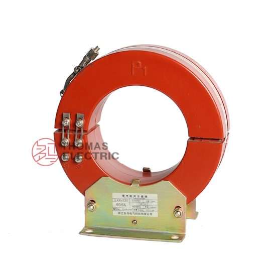
The LXK-120 is a precision-engineered, cast-resin insulated current transformer (CT) rated for 11kV systems per IEC standards, with compatibility for 10kV domestic networks. Designed in accordance with IEC 61869-2 and GB/T 20840.2, it converts high primary currents into standardized secondary signals—typically 1A or 5A—for accurate metering, protection, and monitoring functions. Its construction leverages vacuum pressure impregnation (VPI) epoxy resin technology, which fully encapsulates the magnetic core and windings, eliminating air voids and moisture ingress pathways.
Operating Principle of Cast-Resin Insulation
Cast-resin insulation in the LXK-120 employs a two-stage VPI process where the wound core assembly is first evacuated under vacuum to remove entrapped air, then impregnated with thermosetting epoxy resin under pressure. The assembly is subsequently cured at elevated temperatures (typically 80–120°C) to form a monolithic, non-hygroscopic solid. This structure provides uniform dielectric strength (>28 kV/mm), excellent tracking resistance (CTI >600 V), and mechanical rigidity. Unlike oil-filled CTs, the absence of liquid insulation eliminates fire hazards, leakage risks, and maintenance-intensive oil sampling.
Advantages Over Oil-Immersed Designs
The LXK-120’s cast-resin design offers significant operational advantages: zero risk of flammability (critical for indoor substations), immunity to altitude effects up to 3000 m, and no requirement for periodic oil testing or degassing. Thermal stability is enhanced due to the high thermal conductivity (~0.8 W/m·K) of filled epoxy, allowing consistent performance under continuous overload conditions (up to 1.2× rated current). Additionally, the compact footprint reduces space requirements by 30–40% compared to equivalent oil-immersed units, facilitating retrofitting in constrained switchgear bays.
Typical Applications Overview
This CT is deployed across utility distribution networks, industrial plants, and renewable energy facilities where reliability, accuracy, and minimal maintenance are paramount. Common use cases include feeder protection in 11kV ring main units (RMUs), revenue metering at distribution transformers, and fault current monitoring in solar farm collector circuits. Its robust environmental rating (IP54 when mounted vertically) ensures stable operation in both indoor switchrooms and outdoor pad-mounted enclosures subject to dust, humidity, and temperature cycling from –40°C to +55°C.
Technical Specifications
The LXK-120 adheres strictly to IEC 61869-2 performance envelopes while accommodating Chinese GB/T 20840.2 requirements. Key parameters are validated during type testing and verified during routine production.
| Parameter | Value |
|---|---|
| Rated System Voltage (Ur) | 11 kV (IEC) / 10 kV (GB) |
| Rated Primary Current (Ip) | 50 A to 3000 A (standard steps) |
| Rated Secondary Current (Is) | 1 A or 5 A |
| Accuracy Class (Metering) | 0.2S, 0.5S |
| Accuracy Class (Protection) | 5P10, 5P20, 10P10 |
| Rated Burden | 2.5 VA to 30 VA (per class) |
| Short-Time Thermal Current | 20×Ip for 1 s |
| Dynamic Withstand Current | 50×Ip peak |
| Power Frequency Withstand Voltage | 28 kV rms, 1 min |
| Lightning Impulse Withstand | 75 kV peak (1.2/50 μs) |
| Core Material | Grain-Oriented Electrical Steel (GOES), M6 grade |
| Insulation System | VPI Epoxy Resin, UL 94 V-0 rated |
Standard Service Conditions
The LXK-120 is rated for standard service conditions as defined in IEC 61869-1: ambient temperature range of –40°C to +40°C (with derating above +40°C), relative humidity ≤95% non-condensing, and installation altitude ≤1000 m above sea level. For altitudes between 1000–3000 m, the power frequency withstand voltage must be reduced by 1% per 100 m increment above 1000 m. The unit is suitable for both indoor and outdoor use when installed in IP54-rated enclosures; direct exposure to UV radiation requires optional UV-stabilized resin formulation.
Thermal and Electromagnetic Performance
Thermal design ensures that temperature rise under rated load does not exceed 60 K for windings (measured by resistance method). The GOES core minimizes hysteresis and eddy current losses, achieving excitation voltages ≥150 V at 10% of rated burden for 0.2S class units. Saturation characteristics comply with IEC 61869-2 Annex B: knee-point voltage (Ek) ≥ 2× rated secondary voltage under maximum burden. This guarantees linear response during fault conditions up to the specified accuracy limit factor (e.g., ALF = 10 for 5P10).
Typical Applications
The LXK-120 serves diverse roles in modern power systems, leveraging its high accuracy, compact size, and maintenance-free operation.
Substation Secondary Metering
In 11kV/10kV distribution substations, the LXK-120 provides revenue-grade current signals to digital energy meters compliant with IEC 62053-22. When configured in 0.2S class with 5 A secondary output and 10 VA burden, it achieves measurement uncertainty below ±0.2% over 1–120% of rated current. This enables precise billing for commercial and industrial consumers. The CT is typically mounted directly on circuit breakers or disconnect switches, with shielded twisted-pair cables routed to metering cabinets to minimize electromagnetic interference.
Industrial Power Distribution
Within manufacturing facilities, the LXK-120 supports motor protection relays (e.g., IEC 60255-compliant devices) by delivering scaled current inputs for overload, short-circuit, and ground-fault detection. In 5P20 configuration, it maintains ≤5% composite error at 20× rated current, ensuring reliable tripping during severe faults. Its high dynamic withstand (50×Ip) protects against mechanical stress from close-in short circuits. The resin housing resists chemical vapors common in petrochemical or pulp-and-paper plants, unlike oil-filled alternatives.
Renewable Energy Integration
Solar and wind farms utilize the LXK-120 for grid interconnection monitoring. At inverter output feeders, it supplies data to SCADA systems for real-time power flow analysis and anti-islanding protection. The CT’s low remanence (<10% of saturation flux density) prevents core saturation during DC-offset fault currents—a critical requirement for inverter-based resources. Units are often installed in outdoor combiner boxes with NEMA 4X enclosures, where the cast-resin body withstands thermal cycling from desert heat to coastal humidity without degradation.
Rural and Suburban Distribution Networks
For utility pole-mounted transformers or underground RMUs serving residential areas, the LXK-120 enables cost-effective AMI (Advanced Metering Infrastructure) deployment. Its 1 A secondary option reduces copper losses in long cable runs to centralized metering panels. The compact design fits within standard 10kV switchgear modules (e.g., 375 mm width), simplifying upgrades in legacy networks. Field experience shows >99.5% operational availability over 10 years in tropical climates with annual rainfall exceeding 2000 mm.
Compliance with International Standards
The LXK-120 is engineered to satisfy both global and regional regulatory frameworks, ensuring interoperability and safety.
IEC 61869-2 Certification Requirements
Per IEC 61869-2:2012, the LXK-120 undergoes rigorous type tests including temperature rise, short-circuit withstand, and accuracy verification across burden ranges. Accuracy classes are validated at 5%, 20%, 100%, and 120% of rated current for metering, and at ALF multiples for protection. Dielectric tests require 28 kV rms for 1 minute between primary and secondary/ground, with partial discharge levels <10 pC at 1.2×Um/√3. Every production batch receives routine tests: polarity check, turns ratio verification (±0.5% tolerance), and insulation resistance (>1000 MΩ at 2500 V DC).
Alignment with GB/T 20840.2
Chinese national standard GB/T 20840.2 mirrors IEC 61869-2 but includes additional requirements for seismic resilience (Class II per GB/T 13540) and stricter partial discharge limits (<5 pC). The LXK-120 meets these through reinforced core clamping and optimized resin fill density. Notably, GB/T specifies 10 kV as the nominal system voltage (vs. 11 kV in IEC), though insulation levels remain identical (28 kV/75 kV). Domestic certification requires testing at accredited labs like China Electric Power Research Institute (CEPRI).
Key Differences Between IEC and GB Standards
While both standards align on core performance metrics, GB/T 20840.2 mandates extended thermal endurance testing (1.1×Ip for 8 hours) and higher impulse test counts (15 positive/negative shots vs. IEC’s 5). Marking requirements also differ: GB units must display “GB” logo and Chinese safety warnings. For export models, dual marking (IEC + GB) is applied. Crucially, accuracy verification under DC offset (required for GB grid code compliance) is performed using asymmetric fault simulators, whereas IEC focuses on symmetrical AC conditions.
On-Site Testing Procedures
Post-installation and periodic field tests ensure the LXK-120 operates within design tolerances. All procedures follow IEC 60060-1 and IEEE C57.13.2 guidelines.
Insulation Resistance Test
Using a 2500 V DC megohmmeter, measure resistance between primary conductor and secondary terminals/ground. Acceptance criterion: ≥1000 MΩ at 20°C. Correct for temperature using RT2 = RT1 × 2(T1–T2)/10. Low readings (<100 MΩ) indicate moisture ingress or resin cracking—requiring immediate replacement. Perform before and after dielectric tests to detect insulation damage.
Turns Ratio Test
Apply low-voltage AC (5–50 V) to secondary winding and measure induced primary voltage. Calculate ratio as Vs/Vp; compare to nameplate (e.g., 600:5 = 120:1). Tolerance: ±0.5% for metering classes, ±1.0% for protection. Use a dedicated CT analyzer (e.g., Omicron CT Analyzer) for automated excitation curve plotting. Deviations >2% suggest turn-to-turn shorts or incorrect tap selection.
Polarity Verification
Confirm reducing polarity per IEC 61869-2 Figure 3. Connect DC source (+) to P1, (–) to P2; connect galvanometer between S1 and S2. Momentary closure should produce positive kick on S1. Incorrect polarity causes relay misoperation—especially in differential schemes. Re-test after any terminal rework. Digital multimeters with diode-test mode can substitute for galvanometers in low-voltage checks.
Power Frequency Withstand Voltage Test
Apply 28 kV rms, 50 Hz between primary and grounded secondary/enclosure for 1 minute. Use a calibrated test transformer with overcurrent trip (≤50 mA). Monitor for flashover, excessive leakage current (>1 mA), or audible discharge. Reduce voltage gradually post-test. Never perform if insulation resistance is <500 MΩ. For in-service units, apply 80% of factory test voltage (22.4 kV) per IEEE C57.13.2.
Excitation (Saturation) Characteristic Test
Ramp secondary voltage from 0 to 2× knee-point while measuring excitation current. Plot V-I curve; knee-point is where slope decreases by 45°. For 0.2S class, Ek ≥ 150 V at 10 VA burden. Saturation below spec indicates core damage or shorted turns. This test replaces open-circuit tests used for VTs and is critical for protection CTs to validate ALF compliance.
Preventive Maintenance Guide
Although cast-resin CTs are largely maintenance-free, scheduled inspections prevent latent failures.
Periodic Inspection Protocol
Conduct annual visual and electrical checks: inspect for surface tracking, cracks, or discoloration on resin housing; verify terminal tightness (torque: 15 N·m for M8 studs); clean dust with dry cloth (no solvents). Measure insulation resistance and compare to baseline. In coastal or industrial zones, increase frequency to semi-annual. Document all findings in asset management systems for trend analysis.
Maintenance Intervals and Fault Diagnosis
Replace units exhibiting: insulation resistance drop >50% year-over-year, ratio error >1.5%, or abnormal heating detected via infrared scan (>10 K above ambient). While the LXK-120 has no user-serviceable parts, external connections may loosen due to thermal cycling. Typical failure modes include secondary winding opens (from vibration) or core saturation (from incorrect burden). No internal repairs are permitted—failed units must be replaced per manufacturer warranty terms.
| Interval | Tasks |
|---|---|
| Annual | Visual inspection, IR thermography, insulation resistance test |
| 5-Year | Full suite: ratio, polarity, excitation curve, dielectric test (reduced voltage) |
| Post-Fault | Mandatory ratio and excitation test after any system short circuit |
Conclusion
The LXK-120 11kV cast-resin current transformer represents a benchmark in medium-voltage instrumentation, combining IEC 61869-2-certified accuracy with the ruggedness required for global deployment. Its VPI epoxy resin encapsulation eliminates the fire, leakage, and maintenance liabilities inherent in oil-immersed designs, while the GOES core ensures metrological stability across metering and protection applications. Compliance with both IEC and GB standards facilitates seamless integration into international and domestic grids alike. With a design life of 25–30 years under standard service conditions—and proven field reliability in extreme environments from arid deserts to humid tropics—the LXK-120 delivers long-term operational certainty. Rigorous on-site testing and a disciplined preventive maintenance regimen further safeguard asset integrity, ensuring decades of precise current transformation for critical power system functions.
Frequently Asked Questions (FAQ)
Can the LXK-120 be tested with the secondary winding open?
No. Opening the secondary circuit during primary current flow induces dangerously high voltages (>3 kV) due to core saturation, risking insulation failure and personnel hazard. Always short-circuit secondary terminals before disconnecting loads. Use test blocks with make-before-break contacts for safe meter/relay servicing.
What is the acceptable insulation resistance value for an in-service LXK-120?
Minimum 1000 MΩ at 2500 V DC and 20°C. Values below 500 MΩ warrant investigation; below 100 MΩ require immediate replacement. Correct readings for temperature using the doubling rule: resistance halves per 10°C rise above 20°C.
How often should ratio testing be performed?
Annually for critical protection circuits (e.g., differential relaying), every 3–5 years for metering applications. Always perform after any physical disturbance (e.g., busbar work) or system fault exceeding 10× rated current.
Is the LXK-120 suitable for outdoor installations?
Yes, when mounted in IP54-rated enclosures. The standard UV-resistant resin withstands direct sunlight, but prolonged exposure above 55°C ambient requires derating per IEC 61869-1. Avoid horizontal mounting outdoors to prevent water pooling on terminals.
What burden values are compatible with 0.2S accuracy class?
For 0.2S class, burden must be within 25–100% of rated VA (e.g., 2.5–10 VA for a 10 VA unit). Exceeding max burden increases ratio error; operating below 25% may degrade phase error performance. Always verify total loop impedance (wiring + device) during commissioning.
Can multiple secondary cores be paralleled for higher output?
No. Paralleling cores alters magnetizing impedance and invalidates accuracy certification. Each core must drive its own isolated burden. For higher output needs, select a model with appropriately rated single-core output (e.g., 30 VA instead of 15 VA).