Article Content
Introduction to the SZW-6 Voltage Transformer
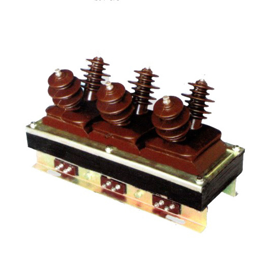
The SZW-6 is a single-phase, indoor/outdoor-rated cast-resin voltage transformer (VT) designed for accurate voltage measurement and reliable protective relay operation in medium-voltage power systems operating at 11kV (IEC standard) or 10kV (domestic Chinese system). As a critical component in substation secondary circuits, it provides galvanically isolated, scaled-down voltage signals proportional to the primary system voltage for metering, monitoring, and protection functions.
Operating Principle of Cast-Resin Insulation
The SZW-6 employs vacuum pressure impregnation (VPI) epoxy resin technology to encapsulate its high-voltage winding and magnetic core assembly. During manufacturing, the wound coil—comprising high-permeability grain-oriented electrical steel (GOES)—is placed in a mold under vacuum to remove air pockets, then injected with thermosetting epoxy resin under pressure. This process yields a monolithic, void-free solid insulation structure with excellent dielectric strength (≥30 kV/mm), superior tracking resistance, and minimal partial discharge (<5 pC at 1.2 × Um/√3). Unlike oil-filled units, the solid resin eliminates fire hazards, leakage risks, and environmental concerns, making it ideal for urban substations, indoor switchgear, and environmentally sensitive installations.
Advantages Over Oil-Immersed Designs
Cast-resin VTs like the SZW-6 offer significant operational and safety benefits compared to traditional oil-immersed counterparts. They are maintenance-free during normal service life due to the absence of liquid insulation that degrades over time. The solid resin provides mechanical robustness against vibration and seismic loads (up to 0.5g), while also resisting moisture ingress even in high-humidity environments (up to 95% RH non-condensing). Additionally, the compact footprint—enabled by higher thermal conductivity of epoxy versus oil—allows for space-efficient integration into ring main units (RMUs) and metal-enclosed switchgear. Crucially, the SZW-6 meets IEC 61869-3 requirements for pollution degree 3 and altitude up to 1,000 m without derating, ensuring consistent performance across diverse geographic conditions.
Typical Applications Overview
The SZW-6 is engineered for dual-purpose use: precision metering (accuracy class 0.2 or 0.5) and protective relaying (accuracy class 3P or 6P). It is commonly deployed in 11kV distribution substations feeding commercial complexes, industrial plants, and renewable energy interconnection points. Its robust design supports continuous operation under unbalanced load conditions and transient overvoltages (e.g., switching surges up to 75 kV peak). With a standard secondary output of 100 V or 100/√3 V, it interfaces seamlessly with digital protective relays, revenue meters, and SCADA systems. The unit’s compliance with both IEC 61869-3 and GB/T 20840.3 ensures interoperability in international and domestic Chinese grid infrastructure projects.
Technical Specifications
The SZW-6 voltage transformer is engineered to meet stringent performance criteria under defined service conditions. Below is a comprehensive specification table followed by environmental and operational parameters.
| Parameter | Value |
|---|---|
| Primary Rated Voltage (Ur) | 11 kV (IEC) / 10 kV (GB) |
| Secondary Rated Voltage | 100 V or 100/√3 V (standard); 110 V optional |
| Voltage Ratio | 11,000/100 V, 11,000/100/√3 V, etc. |
| Accuracy Classes | Metering: 0.2, 0.5; Protection: 3P, 6P |
| Rated Output (per burden) | 10–100 VA (configurable per winding) |
| Insulation Level (Um) | 12 kV |
| Power Frequency Withstand Voltage | 28 kV rms, 1 min (primary to ground) |
| Lightning Impulse Withstand Voltage | 75 kV peak (1.2/50 μs wave) |
| Partial Discharge Level | <5 pC at 1.2 × (12/√3) kV |
| Thermal Class | E (120°C max winding temperature rise) |
| Core Material | Grain-Oriented Electrical Steel (GOES), 0.27 mm thickness |
| Insulation System | VPI Epoxy Resin (Class F, 155°C short-term) |
Standard Service Conditions
The SZW-6 is rated for operation under IEC 60060-1 standard atmospheric conditions: ambient temperature range of –25°C to +40°C, relative humidity ≤95% (non-condensing), and installation altitude ≤1,000 m above sea level. For altitudes between 1,000 m and 3,000 m, voltage withstand values must be derated by 1% per 100 m above 1,000 m. The unit is suitable for both indoor (pollution degree 2) and outdoor (pollution degree 3) environments when mounted with appropriate creepage distance (≥20 mm/kV for 11kV systems). Terminal clearances comply with IEC 61869-3 Table 4, ensuring safe clearance-to-ground distances even under wet conditions.
Electrical Performance Characteristics
Under nominal load (e.g., 30 VA at cos φ = 0.8 lagging), the SZW-6 maintains ratio error within ±0.2% and phase displacement ≤10 minutes for accuracy class 0.2. For protection class 3P, composite error remains below 3% at rated voltage and up to 5× rated voltage during fault conditions. The magnetizing current is typically <0.5% of rated primary current at 1.2× Ur, minimizing burden on the primary circuit. Thermal stability is verified through a 2-hour temperature rise test per IEC 61869-3 Clause 10.3, with winding temperature rise not exceeding 60 K above ambient.
Typical Applications
Substation Secondary Metering
In 11kV primary distribution substations, the SZW-6 provides precise voltage input to revenue-class kWh meters and power quality analyzers. Its 0.2 accuracy class ensures billing compliance per IEC 62053-22, while low phase displacement (<5 arcmin) enables accurate calculation of real/reactive power in three-phase systems. Installed on busbars or feeder circuits, it supports time-of-use tariff structures and demand-side management. The cast-resin construction prevents oil contamination in metering cabinets, a common issue with older oil-filled VTs in compact indoor substations.
Industrial Power Distribution
Heavy industries such as steel mills, chemical plants, and data centers rely on the SZW-6 for both metering and motor protection. In motor control centers (MCCs), it feeds undervoltage relays (e.g., ANSI 27) and overvoltage relays (ANSI 59) with stable secondary signals. The unit’s ability to withstand frequent switching transients—common in capacitor bank switching—is enhanced by its high impulse withstand rating (75 kV). Its compact size allows retrofitting into legacy switchgear without structural modifications.
Renewable Energy Integration
Solar PV and wind farms connecting to 11kV grids use the SZW-6 for grid synchronization and anti-islanding protection. During islanding events, rapid voltage deviation detection requires VTs with minimal response delay and high linearity—attributes inherent in the GOES core and low-loss resin insulation. The SZW-6’s 6P protection class ensures reliable operation during asymmetrical faults near inverter interfaces, where harmonic distortion can challenge conventional VTs.
Rural and Suburban Distribution Networks
In remote areas with limited maintenance access, the SZW-6’s maintenance-free design is critical. Mounted on pole-top transformers or pad-mounted switchgear, it operates reliably despite wide temperature swings and dust exposure. Its IP54-rated terminal box protects secondary connections from rodents and moisture. Utilities in Southeast Asia and Africa specify this model for rural electrification due to its 30-year expected service life and immunity to oil degradation in tropical climates.
Backup and Redundant Systems
Critical facilities like hospitals and airports deploy dual SZW-6 units for N+1 redundancy. One VT serves metering, the other protection, ensuring continuity if one fails. The identical ratio and phase characteristics simplify automatic transfer schemes. Testing protocols include cross-comparison of secondary voltages during routine checks to detect early insulation degradation.
Compliance with International Standards
IEC 61869-3 Certification Requirements
The SZW-6 is fully compliant with IEC 61869-3:2011 “Instrument transformers – Part 3: Additional requirements for inductive voltage transformers.” This includes mandatory type tests: temperature rise, short-circuit withstand (for VTs, simulated via open-circuit thermal stress), electromagnetic compatibility (EMC), and seismic qualification (if applicable). Routine tests per Clause 12 include ratio verification (±0.1% tolerance), polarity check, and power frequency withstand. The manufacturer provides a test report traceable to an ISO/IEC 17025-accredited lab, confirming compliance with all normative clauses.
Alignment with GB/T 20840.3
In China, the SZW-6 meets GB/T 20840.3-2013, which harmonizes with IEC 61869-3 but includes localized requirements. Key differences include: (1) mandatory lightning impulse test at 75 kV (vs. IEC’s 75 kV optional for Um ≤12 kV); (2) stricter partial discharge limits (<3 pC at factory test); and (3) requirement for a nameplate in Chinese characters alongside English. The domestic 10kV system voltage is accommodated via adjusted ratio (10,000/100 V), though the insulation design remains based on 11kV IEC standards to ensure margin.
Testing and Certification Documentation
Each SZW-6 unit ships with a certificate of conformity listing test results for: insulation resistance (>10,000 MΩ at 2,500 V DC), turns ratio error, and burden verification. Type test reports cover 20+ parameters, including thermal stability under 1.5× rated voltage for 8 hours. For export projects, additional certifications (e.g., KEMA, CESI) may be provided. Compliance ensures seamless integration into smart grid architectures governed by IEC 61850, where accurate phasor measurement depends on VT fidelity.
On-Site Testing Procedures
Insulation Resistance Test
Perform using a 2,500 V DC megohmmeter between primary winding and grounded case/secondary terminals. Acceptance criterion: ≥10,000 MΩ at 20°C. Correct for temperature using RT = R20 × 2(20–T)/10. Low readings indicate moisture ingress or resin cracking. Retest after cleaning terminals with isopropyl alcohol if surface contamination is suspected.
Turns Ratio Test
Apply 100–200 V AC to primary and measure secondary voltage with a calibrated voltmeter (0.1% accuracy). Calculate actual ratio = Vp/Vs. Tolerance: ±0.1% for metering class, ±0.3% for protection class. Deviations >0.5% suggest turn-to-turn shorts or winding damage. Use a dedicated ratio tester (e.g., Omicron CT Analyzer) for automated comparison against nameplate values.
Polarity Verification
Confirm reducing polarity (standard for IEC VTs) using the DC kick method: connect a 6–12 V battery momentarily to primary (H1+, H2–). A DC voltmeter on secondary (X1+, X2–) should show a positive deflection on make and negative on break. Incorrect polarity causes 180° phase reversal, leading to false tripping in directional relays.
Power Frequency Withstand Voltage Test
Apply 28 kV rms at 50 Hz between primary and grounded case for 1 minute. Use a calibrated test transformer with overcurrent trip (≤100 mA). No flashover or disruptive discharge permitted. For field testing, reduce to 80% (22.4 kV) if the unit has been in service >1 year. Always disconnect secondary burdens and ground unused terminals.
Open-Circuit Characteristic Test
Gradually increase primary voltage from 0 to 1.5× Ur (16.5 kV) while measuring secondary voltage and excitation current. Plot Vs vs. Iexc. A sharp current rise before 1.2× Ur indicates core saturation or insulation weakness. At 1.2× Ur, excitation current should be <1% of rated primary current. This test validates magnetic circuit integrity post-transport or after fault exposure.
Preventive Maintenance Guide
Annual Visual and Functional Inspection
Inspect for: (1) surface cracks or UV degradation (outdoor units); (2) terminal corrosion or loose bolts (torque: 15 N·m for M10 studs); (3) discoloration indicating overheating; (4) moisture in terminal box (check desiccant if present). Verify secondary voltage under load matches expected value (±2%). Clean housing with mild detergent; avoid solvents that attack epoxy. Record insulation resistance annually to establish trend data.
Five-Year Comprehensive Maintenance
Every 60 months, perform: (1) full ratio and polarity retest; (2) partial discharge measurement (if portable PD detector available; limit: <10 pC at 1.2× Ur/√3); (3) burden verification using calibrated load bank; (4) torque check on all mechanical fasteners. Replace gaskets on terminal box if hardened. If cumulative ratio error exceeds 0.4%, consider replacement—even if within tolerance—as it may indicate progressive core aging.
Fault Diagnosis and Troubleshooting
Common failure modes: (1) **Zero secondary output** – check for open secondary fuse or broken lead; (2) **High ratio error** – likely turn-to-turn short (confirmed by elevated excitation current); (3) **Overheating** – excessive burden or harmonic resonance (verify connected load ≤ rated VA); (4) **Cracking sounds** – partial discharge activity requiring immediate isolation. Never operate with secondary open-circuited during primary energization—it induces dangerous overvoltages. Maintain a logbook with test dates, personnel, and instrument IDs for audit compliance.
| Maintenance Interval | Tasks |
|---|---|
| Monthly (Remote) | SCADA voltage trend review |
| Annually | Visual inspection, IR test, secondary voltage check |
| Every 5 Years | Full electrical tests, PD scan, mechanical integrity check |
| After Major Fault | Withstand test, ratio test, open-circuit curve |
Conclusion
The SZW-6 11kV cast-resin voltage transformer represents a benchmark in reliability, accuracy, and safety for modern medium-voltage networks. Its VPI epoxy resin insulation system eliminates the fire and environmental risks associated with oil-filled designs, while the GOES core ensures high magnetic efficiency and low losses across the operational voltage range. Compliance with both IEC 61869-3 and GB/T 20840.3 guarantees global acceptance and seamless integration into diverse grid architectures—from urban smart substations to remote renewable sites. Rigorous factory testing and straightforward field verification procedures support decades of trouble-free operation, with an expected service life of 25–30 years under standard conditions. The dual capability for precision metering (0.2 class) and robust protection (3P/6P) makes it a versatile solution for utilities and industrial operators seeking to minimize lifecycle costs without compromising on performance. When maintained according to the prescribed schedule—including annual insulation checks and quinquennial comprehensive diagnostics—the SZW-6 delivers consistent metrological integrity and fault resilience, forming a dependable cornerstone of secondary system reliability in 11kV infrastructure worldwide.
Frequently Asked Questions (FAQ)
Q1: Can the SZW-6 be used on a 10kV domestic system?
Yes. While rated for 11kV per IEC standards, the SZW-6 is commonly deployed on 10kV Chinese distribution networks. The insulation level (Um = 12 kV) provides adequate margin, and the voltage ratio is adjusted accordingly (e.g., 10,000/100 V).
Q2: What is the maximum allowable burden for accuracy class 0.2?
For 0.2 class, the connected burden must not exceed the rated output specified on the nameplate (typically 30 VA). Exceeding this increases ratio error beyond ±0.2%. Always verify total burden—including relay coils, meter inputs, and wiring resistance—during commissioning.
Q3: Is the SZW-6 suitable for outdoor installation?
Yes. The cast-resin housing is UV-stabilized and rated for pollution degree 3. Mount with terminals facing downward to prevent water accumulation, and ensure creepage distance ≥240 mm for 11kV systems in coastal areas.
Q4: How often should insulation resistance be tested?
Annually as part of preventive maintenance. A sudden drop >50% from baseline indicates insulation deterioration and warrants further investigation (e.g., partial discharge test).
Q5: Can multiple secondary windings be loaded simultaneously?
Yes, but the sum of individual burdens must not exceed the thermal rating of the VT. Each winding’s burden contributes to total core excitation; overloading causes saturation and accuracy loss.
Q6: What test voltage is used for field withstand testing?
For in-service units, apply 80% of factory test voltage: 22.4 kV rms (50 Hz) for 1 minute between primary and ground. Ensure all secondary terminals are short-circuited and grounded during the test.