Article Content
For Substation Metering & Protection: XGW-12 11kV Cast-Resin Current Transformer per IEC 61869-2
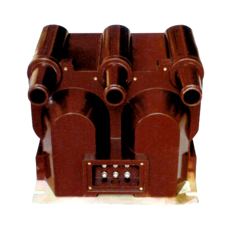
Introduction to the XGW-12 Current Transformer
The XGW-12 is a high-reliability, cast-resin insulated current transformer (CT) engineered for accurate current measurement and protective relay coordination in medium-voltage power systems operating at 11kV (IEC standard) or 10kV (domestic Chinese grid equivalent). Designed in strict accordance with IEC 61869-2 and GB/T 20840.2, this instrument transformer leverages vacuum pressure impregnation (VPI) epoxy resin technology to deliver superior dielectric strength, environmental resilience, and long-term operational stability.
Operating Principle of Cast-Resin Insulation
Cast-resin insulation in the XGW-12 utilizes a two-component epoxy system cured under vacuum and pressure to fully encapsulate the primary conductor, secondary windings, and magnetic core. This process eliminates air voids and moisture ingress pathways, resulting in a homogeneous dielectric structure with high partial discharge inception voltage (>20 kV at 50 Hz). The VPI technique ensures uniform resin distribution around complex geometries, particularly critical at high-field regions such as winding terminations and core joints. Unlike oil-filled alternatives, the solid epoxy matrix provides inherent fire resistance (UL 94 V-0 rated), zero leakage risk, and immunity to ambient humidity—making it ideal for both indoor switchgear and outdoor pole-mounted installations. The thermal conductivity of the resin (~0.8 W/m·K) also facilitates efficient heat dissipation during transient overloads, maintaining core performance within specified accuracy limits.
Advantages Over Oil-Immersed Designs
Compared to traditional oil-immersed CTs, the XGW-12’s cast-resin construction offers significant operational and safety benefits. First, it eliminates flammability hazards, satisfying stringent fire codes in urban substations and industrial facilities. Second, the absence of liquid insulation removes maintenance burdens associated with oil sampling, degassing, and tank sealing integrity checks. Third, the compact mechanical profile—enabled by higher dielectric strength of epoxy versus oil-paper systems—reduces footprint by up to 30%, facilitating retrofitting in space-constrained switchgear bays. Additionally, cast-resin CTs exhibit lower temperature sensitivity; their ratio error remains stable across -40°C to +55°C ambient ranges, whereas oil viscosity changes can induce measurement drift in older designs. Finally, the XGW-12’s monolithic structure resists vibration and seismic loads better than oil-filled units, which may suffer from internal winding displacement due to fluid sloshing during dynamic events.
Typical Applications Overview
The XGW-12 is deployed across diverse power infrastructure segments requiring precise current transformation for metering, revenue billing, and protective relaying. In utility substations, it interfaces with digital multifunction meters and numerical relays for feeder monitoring and fault detection. Industrial plants use it for motor protection circuits and energy management systems, where its high short-time thermal withstand capability (up to 40 kA for 1 second) ensures survival during downstream faults. Renewable integration projects—particularly solar farms and wind substations—leverage its low remanence characteristics to prevent core saturation during asymmetrical fault recovery. Rural distribution networks benefit from its maintenance-free operation over decades, reducing lifecycle costs in remote locations with limited technical staffing.
Technical Specifications
The XGW-12 is engineered to meet exacting electrical and environmental performance criteria essential for reliable operation in 11kV distribution networks. All parameters are validated per IEC 61869-2 test protocols and certified against GB/T 20840.2 requirements.
Rated Electrical Parameters
The transformer features a primary voltage rating of 11kV (system voltage) with a corresponding highest voltage for equipment (Um) of 12kV. Standard current ratios include 50/5, 100/5, 200/5, 400/5, 600/5, and 800/5 A, with dual-ratio options available upon request. Accuracy classes are designated per application: Class 0.5S or 0.2S for revenue metering, and 5P10 or 5P20 for protection functions. Rated burden values range from 5 VA to 30 VA at 5 A secondary current, with phase displacement maintained below ±10 minutes for Class 0.5S under 25%–100% of rated current. The insulation level complies with IEC 60071-1: power frequency withstand voltage of 28 kV rms for 1 minute and lightning impulse withstand of 75 kV peak (1.2/50 µs waveform). Short-circuit thermal withstand is rated at 40 kA for 1 s, while dynamic withstand exceeds 100 kA peak.
Core and Insulation Materials
The magnetic circuit employs grain-oriented electrical steel (GOES) with a maximum core loss of 1.0 W/kg at 1.7 T and 50 Hz, ensuring minimal excitation current and high linearity under normal load conditions. Secondary windings consist of enameled copper wire (Class H insulation, 180°C rating) wound directly onto the core leg and potted within the resin matrix. The primary conductor is a solid copper bar or tubular busbar, sized to handle continuous current without exceeding 65 K temperature rise above ambient. The cast-resin compound is formulated with alumina trihydrate filler to enhance tracking resistance (CTI > 600 V) and UV stabilizers for outdoor durability. Terminal blocks are made of flame-retardant polyamide (PA66) with IP2X finger-safe enclosures.
Standard Service Conditions
The XGW-12 operates reliably under the following environmental conditions: ambient temperature range of -40°C to +55°C, relative humidity up to 100% (condensing permitted), and installation altitude not exceeding 1,000 m above sea level. For altitudes between 1,000 m and 3,000 m, derating factors apply per IEC 60071-2—specifically, a 1% reduction in withstand voltage per 100 m above 1,000 m. The unit is suitable for both indoor (pollution degree 2) and outdoor (pollution degree 3) applications, with hydrophobic surface properties preventing flashover under wet contamination. Seismic qualification includes horizontal acceleration of 0.3g (Zone 3 per IEEE 693), verified through shake-table testing.
Typical Applications
The XGW-12’s robust design and precision performance make it suitable for a wide array of power system configurations demanding dependable current transformation.
Substation Secondary Metering
In 11kV/10kV distribution substations, the XGW-12 provides accurate current input to revenue-class energy meters (e.g., IEC 62053-22 compliant devices). Its Class 0.2S accuracy ensures billing fidelity even at 1% of rated current—a critical requirement for detecting low-load theft or standby consumption. The low phase error (<±5 minutes at 20%–120% In) minimizes reactive energy measurement uncertainty. Installed on outgoing feeders, it enables real-time load profiling and demand-side management via SCADA systems. The cast-resin housing resists electromagnetic interference from adjacent switchgear, preserving signal integrity over shielded twisted-pair cables routed to metering cabinets.
Industrial Power Distribution
Within manufacturing facilities, the XGW-12 integrates with motor protection relays (e.g., ANSI 50/51 functions) on 10kV motor feeders rated up to 2 MW. Its 5P20 accuracy class guarantees correct operation during high-magnitude faults (up to 20× rated current) without saturation-induced ratio errors. The high thermal withstand capability allows survival during prolonged motor start-up inrush (typically 6–8× In for 10–30 seconds). In arc furnace or welding plant environments, the solid insulation prevents carbon tracking from conductive dust, a common failure mode in oil-filled CTs.
Renewable Energy Integration
Solar photovoltaic (PV) substations utilize the XGW-12 on the AC side of inverters to monitor export power and detect islanding conditions. Its fast transient response (<10 ms rise time) captures rapid current changes during cloud-edge effects or grid disconnection events. The low remanence (<10% of saturation flux density after 10× In interruption) ensures immediate readiness for subsequent fault cycles—critical in microgrids with frequent switching. Similarly, in wind farm collector systems, it supports vector shift and rate-of-change-of-frequency (ROCOF) protection schemes requiring phase-coherent current data.
Rural and Suburban Distribution Networks
For overhead line sections in rural electrification projects, the XGW-12 is mounted on poles or pad-mounted transformers to supply data to distribution automation terminals (DATs). Its maintenance-free nature eliminates the need for periodic oil top-ups or dielectric tests in hard-to-access locations. The IP54-rated terminal box protects secondary connections from rain and dust ingress, while the UV-stabilized resin prevents embrittlement under prolonged solar exposure. In suburban ring-main units (RMUs), it enables automated fault location, isolation, and service restoration (FLISR) by providing synchronized current phasors to intelligent electronic devices (IEDs).
Compliance with International Standards
The XGW-12 is certified to global and regional standards governing instrument transformer performance, safety, and interoperability.
IEC 61869-2 Compliance Details
IEC 61869-2 specifies general requirements for electromagnetic current transformers, including definitions, test methods, and marking rules. The XGW-12 meets all mandatory clauses: ratio error and phase displacement are verified at 5%, 20%, 100%, and 120% of rated current per Table 2 of the standard. Composite error for protection classes is measured using the indirect method (IEC 61869-2 Annex C), with acceptance criteria of ≤10% for 5P class at specified accuracy limit factor (ALF). Partial discharge levels are tested at 1.2 Um/√3 (≈8.3 kV) and must remain below 10 pC—well under the 50 pC limit. Temperature rise tests confirm that windings do not exceed 60 K above ambient under continuous rated current.
Alignment with GB/T 20840.2
GB/T 20840.2 is the Chinese national adoption of IEC 61869-2, with minor editorial differences but identical technical substance. Key alignment points include identical accuracy class definitions (0.2S, 0.5S, 5P10, etc.), same insulation coordination levels (28 kV power frequency, 75 kV lightning impulse), and equivalent short-circuit withstand ratings. However, GB/T 20840.2 mandates additional type tests for pollution performance per GB/T 4585 (salt fog test), which the XGW-12 passes with a minimum creepage distance of 240 mm for 12kV class (equivalent to 20 mm/kV). Domestic certification requires submission to China Quality Certification Center (CQC) with factory audit records.
Testing and Certification Requirements
Full type testing per IEC 61869-2 includes: temperature rise, short-time current, peak withstand current, insulation power frequency, lightning impulse, partial discharge, accuracy verification, and thermal stability. Routine tests performed on every unit include: visual inspection, power frequency withstand (at 80% of type test value), polarity check, and ratio verification. Sample tests (per batch) cover partial discharge and accuracy. Certification documentation includes a Test Report issued by an ISO/IEC 17025-accredited lab and a Declaration of Conformity referencing both IEC 61869-2 and GB/T 20840.2.
On-Site Testing Procedures
Post-installation and periodic field tests ensure the XGW-12 maintains integrity and accuracy throughout its service life.
Insulation Resistance Test
Measure insulation resistance between primary-to-secondary, primary-to-ground, and secondary-to-ground using a 2,500 V DC megohmmeter. Acceptance criterion: ≥1,000 MΩ at 20°C. Correct for temperature using RT = R20 × 2(20−T)/10. Values below 500 MΩ indicate moisture ingress or resin degradation. Perform before and after power frequency withstand tests to detect insulation damage.
Turns Ratio Test
Apply a low-voltage AC source (50–100 V) to the secondary winding and measure induced primary voltage (open-circuit). Calculate actual ratio as Vsec/Vprim. Compare to nameplate ratio; tolerance must be within ±0.2% for metering classes and ±1.0% for protection classes. Alternatively, use a dedicated turns ratio tester injecting 1–5 A into the primary and measuring secondary current. Ensure secondary burden does not exceed 10% of rated VA during test.
Polarity Verification
Confirm reducing polarity using the DC kick method: connect a 6–12 V battery momentarily between P1 and P2. Observe analog ammeter deflection on S1–S2; positive kick indicates correct polarity (S1 corresponds to P1). Digital testers automate this with pulse injection and phase-angle detection. Incorrect polarity causes 180° phase reversal, leading to false tripping in differential protection schemes.
Power Frequency Withstand Voltage Test
Apply 28 kV rms at 50 Hz between primary and grounded secondary/enclosure for 1 minute. Use a calibrated HV test set with automatic trip at 5 mA leakage current. Gradually ramp voltage (≤2 kV/s) to avoid transient overstress. Failure is indicated by flashover, sustained arcing, or abrupt current increase. This test validates dielectric integrity after transportation or installation stress.
Short-Circuit Test (for CT)
Unlike VTs, CTs require verification of thermal and dynamic withstand capability indirectly. Inject 10× rated current into primary for 1 second using a portable short-circuit generator. Monitor secondary current waveform for distortion indicating core saturation. Post-test, repeat insulation resistance and ratio tests to confirm no mechanical displacement or winding deformation occurred. Acceptable if all parameters remain within initial tolerances.
Preventive Maintenance Guide
A structured maintenance regimen maximizes the XGW-12’s 25–30 year service life while minimizing unplanned outages.
Periodic Inspection Protocol
Conduct annual visual and electrical inspections: check for surface cracks, tracking marks, or discoloration on the resin housing; verify terminal tightness (torque: 2.5 N·m for M6 screws); inspect gasket seals on terminal boxes; and perform insulation resistance and ratio spot-checks. Clean external surfaces with non-abrasive detergent to remove salt or industrial deposits. Record all readings in a condition-monitoring log for trend analysis.
Maintenance Intervals and Fault Diagnosis
Every 5 years, perform comprehensive diagnostics: partial discharge mapping (using HFCT sensors), thermal imaging under load (hot spots >10 K above ambient warrant investigation), and full accuracy re-verification per IEC 61869-2. Common faults include: open secondary circuits (causing dangerous overvoltages), core lamination shorts (evidenced by elevated excitation current), and moisture-induced surface leakage (low insulation resistance with high humidity correlation). If ratio error exceeds ±0.5% (metering) or ±2% (protection), replace the unit—field repair of cast-resin CTs is not feasible.
| Maintenance Interval | Activities |
|---|---|
| Annual | Visual inspection, terminal torque check, IR test, ratio spot-check |
| 5-Year | Partial discharge test, thermal scan, full accuracy verification, pollution layer assessment |
| After Major Fault | Dynamic withstand validation, insulation integrity retest, mechanical mounting inspection |
Conclusion
The XGW-12 11kV cast-resin current transformer represents a benchmark in reliability, accuracy, and compliance for modern power systems. By leveraging advanced VPI epoxy resin technology and GOES silicon steel cores, it delivers stable metrological performance across extreme environmental conditions—from arid deserts to humid coastal zones—without the operational liabilities of oil-filled alternatives. Its dual certification to IEC 61869-2 and GB/T 20840.2 ensures seamless integration into both international and domestic grid infrastructures, supporting applications ranging from precision revenue metering to high-speed protection in renewable-rich networks. Rigorous factory testing and straightforward field verification procedures guarantee consistent quality, while the maintenance-free design significantly reduces total cost of ownership over its expected 25–30 year service life. For utilities and industrial operators seeking a future-proof solution for 10kV/11kV current transformation, the XGW-12 combines engineering excellence with regulatory assurance, making it a cornerstone component in resilient and intelligent distribution systems.
Frequently Asked Questions (FAQ)
Q1: Can the XGW-12 be used on a 10kV system even though it’s rated 11kV?
Yes. The 11kV rating aligns with IEC system voltage standards, while 10kV is the nominal voltage in many domestic grids (e.g., China). The XGW-12’s Um of 12kV provides adequate insulation margin for 10kV operation.
Q2: What is the maximum allowable secondary burden for a 300/5A, 5P20 XGW-12?
For 5P20 class, the rated burden must not exceed the value marked on the nameplate (typically 15 VA or 30 VA). Exceeding this burden increases composite error beyond 10% at 20× rated current, risking protection misoperation.
Q3: Is it safe to leave the secondary winding open-circuited during maintenance?
No. An open secondary on a live CT induces dangerously high voltages (several kV) due to unopposed magnetizing current. Always short-circuit secondary terminals with a dedicated shorting link before disconnecting metering or relay circuits.
Q4: How often should partial discharge testing be performed?
PD testing is recommended every 5 years or after exposure to severe overvoltage events (e.g., lightning strikes). Baseline measurements should be taken after commissioning for comparison.
Q5: Does the XGW-12 require drying or conditioning before first energization?
No. Cast-resin CTs are hermetically sealed during manufacturing and do not absorb moisture. They can be energized immediately after installation without pre-conditioning.
Q6: Can multiple secondary windings share the same core in the XGW-12?
Yes. Multi-core variants are available with separate windings for metering (0.2S) and protection (5P20), each optimized for its specific burden and accuracy requirements without mutual interference.