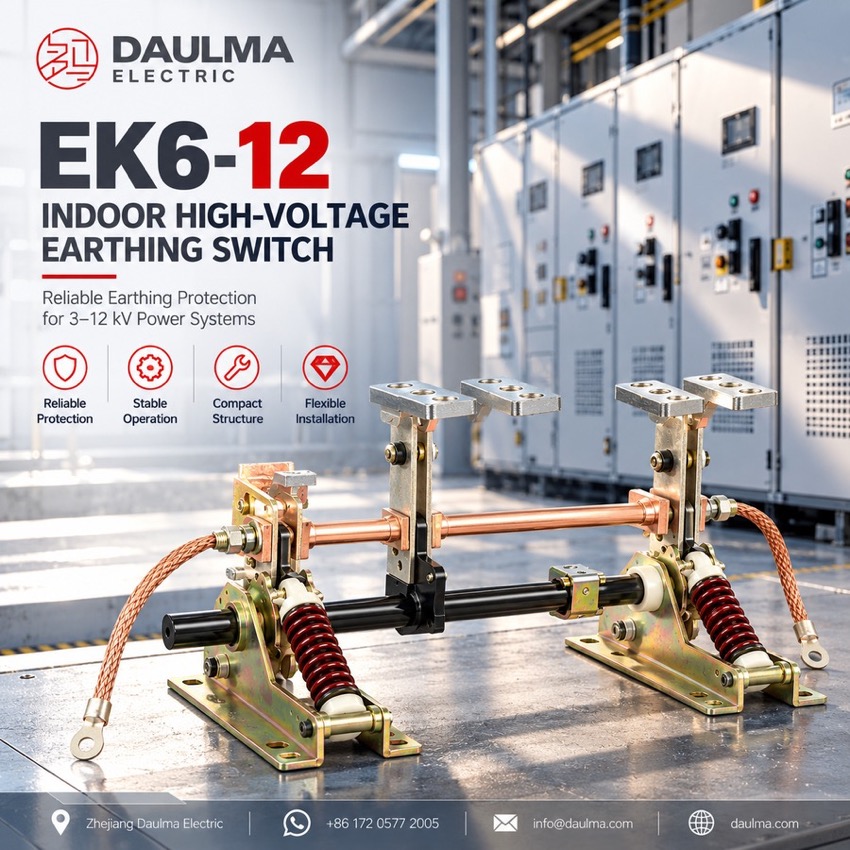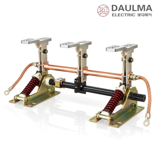
EK6-12/31.5 Indoor High-Voltage Earthing Switch for Switchgear Cubicle - featured

EK6-12/31.5 Indoor High-Voltage Earthing Switch for Switchgear Cubicle

EK6-12/31.5 Indoor High-Voltage Earthing Switch, 12 kV

  • Indoor earthing switch for 3 kV to 12 kV systems
  • Rated short-time withstand current of 31.5 kA
  • Three poles on one shaft, single manual stroke
  • Mechanism assembled for left- or right-hand use
  • Five frames, phase-centre 150 mm up to 275 mm
  • Conforms to GB 1985 and IEC 129, optional G type

Product Overview

The EK6-12/31.5 is an indoor high-voltage earthing switch for 3-12 kV, 50 Hz three-phase systems, fitted in metal-enclosed switchgear to bond a de-energised circuit to earth and guard maintenance work against re-energising. Three rotating earth knives with copper contacts ride on a galvanised steel frame, coupled to one shaft so one manual stroke closes all poles; the mechanism assembles left- or right-hand and interlocks with the disconnector or breaker. Rated 12 kV with 31.5 kA short-time withstand, it comes in five frames of 150-275 mm phase-centre distance, to GB 1985 and IEC 129.

Product Display
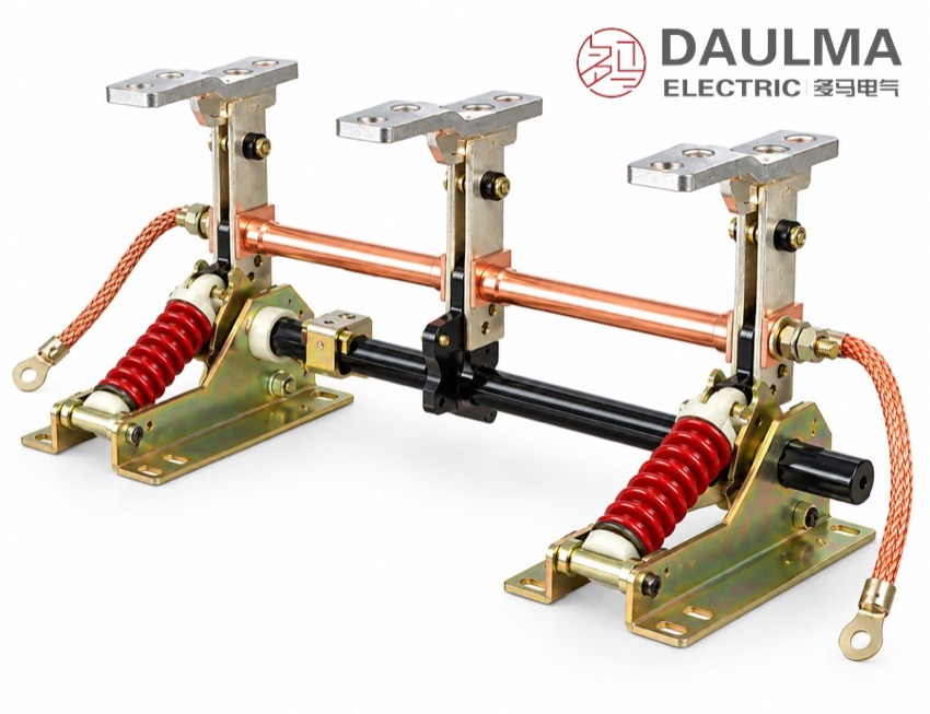
EK6-12/31.5 Indoor High-Voltage Earthing Switch for Switchgear Cubicle - display

EK6-12/31.5 Indoor High-Voltage Earthing Switch for Switchgear Cubicle - poster_display

Model Designation

EK6-12/31.5 Indoor High-Voltage Earthing Switch for Switchgear Cubicle - model

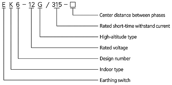
Model format: E K 6 – 12 (G) / 31.5 – □

  • E – earthing switch
  • K – indoor installation
  • 6 – design sequence number
  • 12 – rated voltage, kV
  • (G) – high-altitude version, optional
  • 31.5 – rated short-time withstand current, kA (printed 315 on the designation chart)
  • □ – phase-centre distance, mm: 150 / 210 / 230 / 250 / 275
  • Example: EK6-12/31.5-230 is the 230 mm frame; EK6-12/31.5G is the high-altitude version on the same frame

Service Conditions

  • Ambient air temperature: upper limit +40 °C, lower limit -10 °C
  • Storage and transport: permitted down to -30 °C
  • Altitude: not exceeding 1000 m
  • Seismic intensity: not above 8
  • Site free from flammable or explosive hazards, severe dust, chemical corrosion and violent vibration

Construction

The switch is built as three earthing poles on a galvanised steel base frame, each pole carrying a rotating earthing knife on a high-strength support insulator with copper contacts. The three knives are coupled to one operating shaft driven by a simple manual mechanism, so a single stroke closes or opens all poles together, and the mechanism is assembled for left-hand or right-hand operation to suit the cubicle layout; flexible copper braid connections link the earth circuit to each pole.

The switch earths only: it is closed after the circuit has been isolated and proved de-energised, and it carries and closes against the short-time withstand current without any interrupting capability. It is interlocked with the associated disconnector or circuit breaker, which provides the visible break, and its performance conforms to GB 1985 for AC high-voltage disconnectors and earthing switches and to IEC 129.

Technical Data

Item Unit Data
Rated voltage kV 12
Rated frequency Hz 50
System voltage applied kV 3 – 12
Rated short-time withstand current kA 31.5
Phase-centre distance (five tabulated frames) mm 150 / 210 / 230 / 250 / 275
Rated current, peak withstand current, short-circuit duration, insulation level — not published; per technical agreement and nameplate
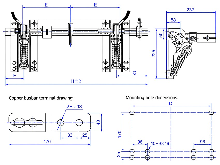
Selection note: Take the phase-centre distance from the busbar or cable routing of the cubicle; the five frames cover 150, 210, 230, 250 and 275 mm. Check the overall width H and the mounting-hole width D against the panel, since both grow with the spacing, and state left-hand or right-hand operation to match the handle position on the cubicle front. Order the G version for altitudes above 1000 m, and remember that an earthing switch does not isolate: pair it with a disconnector or circuit breaker that provides the visible break.

Standards

The performance of the EK6-12/31.5 series conforms to GB 1985 for AC high-voltage disconnectors and earthing switches and to IEC 129. The catalogue page carries no rated-parameter table, so the rated current, the rated peak withstand current, the duration of the 31.5 kA short-time withstand current and the power-frequency and lightning impulse withstand voltages are fixed by the technical agreement and stated on the nameplate of the delivered switch.

Technical note: The designation chart prints the short-time withstand figure as 315 while the product heading and the dimension table use 31.5; both refer to the same 31.5 kA. Catalogue dimensions are for cubicle preparation only – where the fit into an existing cubicle is critical, order against the certified dimensional drawing, and the technical agreement and nameplate govern the ratings.

Installation & Dimensions

Installation Diagram
EK6-12/31.5 Indoor High-Voltage Earthing Switch for Switchgear Cubicle - installation

Fix the frame to the cubicle structure through the slotted mounting holes, set the poles to the phase-centre distance of the busbar in use, and bond the frame to the cubicle earth circuit. Couple the operating shaft to the mechanism on the side the panel allows, then operate the switch by hand and check that every pole reaches the full closed position with the knives seated on their contacts. Bolt the copper terminal plate of the earthed circuit to the terminals and verify the interlock with the associated isolating switch or circuit breaker before the switch is returned to service.

Model E (mm) F (mm) G (mm) H (mm) D (mm)
EK6-12/31.5-150 150 75 160 535 396
EK6-12/31.5-210 210 50 185 655 516
EK6-12/31.5-230 230 50 185 695 556
EK6-12/31.5-250 250 50 185 735 596
EK6-12/31.5-275 275 50 210 810 646
Safety notice: An earthing switch may only be closed onto a circuit that has been isolated and proved de-energised. The EK6-12/31.5 is interlocked with the associated disconnector or circuit breaker so that the earth knives cannot close onto a live circuit and the circuit cannot be re-energised while it is earthed. It carries and closes against short-time current but breaks no load; keep the interlocks in service and let qualified personnel operate and maintain the switch with the frame bonded to the cubicle earth circuit.

FAQs

E stands for the earthing switch and K for indoor installation, 6 is the design sequence number and 12 the rated voltage in kV. The figure after the slash is the rated short-time withstand current in kA, printed as 315 on the designation chart and as 31.5 in the heading, and the last field gives the phase-centre distance in mm; an optional G marks the high-altitude version.

After the circuit has been isolated and proved de-energised, the closed earth knives bond that circuit to the earthing network of the cubicle. This holds the equipment at earth potential while it is worked on and protects maintenance staff against accidental re-energising or induced voltage.

Five frames are tabulated with phase-centre distances of 150, 210, 230, 250 and 275 mm, set by the busbar spacing or the cable routing of the cubicle. The overall width H and the mounting-hole width D grow with the spacing, from 535 mm and 396 mm on the smallest frame to 810 mm and 646 mm on the largest.

No. It carries and closes against the short-time withstand current but has no interrupting capability of any kind. It may be operated only after the associated circuit breaker or disconnector has opened the circuit, and the two are interlocked so the earthing knife cannot close onto a live circuit.

G is the high-altitude version of the same frame, ordered when the site lies above the 1000 m for which the standard switch is rated. The catalogue page carries no rated-parameter table, so beyond the 12 kV rating and the 31.5 kA short-time withstand current the rated current, peak withstand, duration and insulation level are fixed by the technical agreement and given on the nameplate.

State the model, rated voltage, phase spacing, mounting position and whether the mechanism is operated from the left or the right; special requirements are settled with the factory. Service conditions are ambient air from -10 °C to +40 °C, storage and transport down to -30 °C, altitude up to 1000 m, seismic intensity not above 8, and a site free from flammable or explosive hazards, severe dust, chemical corrosion and violent vibration.

Inquiry for EK6-12/31.5 Indoor High-Voltage Earthing Switch for Switchgear Cubicle:

Send your project requirements. Our team will reply with technical details and quotation.

Fast response Technical support OEM / ODM