Contenido del artículo
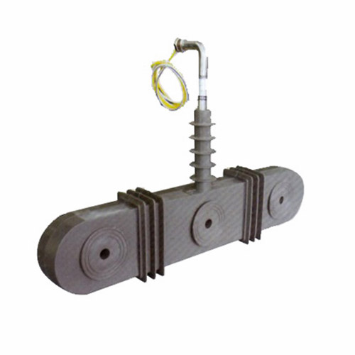
For Substation Metering & Protection: ZW-10 11kV Cast-Resin Current Transformer per IEC 61869-2
Introduction to the ZW-10 Current Transformer
The ZW-10 is a medium-voltage cast-resin current transformer (CT) engineered for reliable operation in 11kV systems (corresponding to domestic 10kV nominal voltage networks). Designed in strict compliance with IEC 61869-2 and GB/T 20840.2, this instrument transformer converts high primary currents—ranging from 50 A to 4000 A—into standardized secondary outputs of 1 A or 5 A, enabling accurate interfacing with protective relays, revenue-grade meters, SCADA systems, and power quality analyzers.
Cast-Resin Insulation Technology
The ZW-10 employs vacuum pressure impregnation (VPI) epoxy resin encapsulation, which fully embeds the GOES (grain-oriented electrical steel) core and copper windings in a homogeneous, void-free dielectric matrix. This process eliminates air pockets that could lead to partial discharges under sustained operating voltages. The cured resin exhibits a relative permittivity of approximately 3.8 and volume resistivity exceeding 1×10¹⁴ Ω·cm at 20°C. Unlike oil-filled alternatives, the cast-resin design is non-flammable, requires no maintenance of insulating fluid, and resists tracking even in polluted coastal or industrial environments. The thermal class of the insulation system is F (155°C), permitting continuous operation at ambient temperatures up to 40°C with a 10K temperature rise margin under rated load.
Advantages Over Oil-Immersed Designs
Compared to traditional oil-immersed CTs, the ZW-10 offers superior environmental resilience and safety. Its solid insulation eliminates risks of oil leakage, fire hazard, or PCB contamination. The compact mechanical footprint reduces space requirements in switchgear cubicles by up to 30%. Additionally, the absence of breathing mechanisms prevents moisture ingress, ensuring stable dielectric performance over decades. The unit’s creepage distance exceeds 25 mm/kV (minimum 275 mm for 11kV), satisfying pollution degree III requirements per IEC 60815. These attributes make the ZW-10 particularly suitable for indoor GIS installations, urban substations, and renewable energy plants where fire codes restrict flammable materials.
Typical Application Overview
The ZW-10 is deployed across utility distribution networks, industrial facilities, and grid-connected photovoltaic farms. In 10kV/11kV ring-main units (RMUs), it provides inputs for overcurrent (50/51) and earth-fault (50N/51N) protection schemes. In commercial buildings, it enables tenant submetering with 0.5S or 0.2S accuracy classes. Its robust short-time thermal withstand capability (e.g., 20 kA for 1 s) ensures survival during downstream faults without degradation. The transformer supports both single-ratio and multi-tap configurations, allowing field adaptation to varying load profiles without hardware replacement.
Technical Specifications
The ZW-10 is engineered to meet stringent electrical and environmental performance criteria essential for modern power systems.
Rated Electrical Parameters
Key electrical ratings include: primary voltage class 11kV (system voltage 10kV); primary current options from 50/1 A to 4000/5 A; secondary current standardization at 1 A or 5 A; accuracy classes of 0.2, 0.5, 1, 3P, and 5P for metering and protection; rated burden from 2.5 VA to 30 VA depending on class; and insulation level defined by power frequency withstand voltage of 28 kV rms for 1 minute and lightning impulse withstand of 75 kV peak (1.2/50 μs waveform). The instrument security factor (FS) for metering cores is ≤5, while the accuracy limit factor (ALF) for protection cores ranges from 5 to 30. Thermal short-time current rating is typically 20–25 kA for 1 second, with dynamic withstand up to 50 kA peak.
Environmental and Mechanical Ratings
The ZW-10 operates reliably under standard service conditions: ambient temperature range of –25°C to +40°C; relative humidity up to 95% non-condensing; altitude ≤1000 m above sea level (with derating above 1000 m per IEC 60071-1); and seismic zone up to 0.3g horizontal acceleration. The housing is UV-stabilized cycloaliphatic epoxy resin with a smooth surface finish to minimize dust accumulation. Mounting is via M12 stainless steel studs or flange brackets compatible with standard switchgear busbar arrangements. The unit weighs approximately 12–18 kg depending on ratio and core configuration.
Core and Winding Construction
The magnetic circuit utilizes high-permeability GOES laminations (grade M4 or equivalent) with interlaminar insulation to reduce eddy current losses. Core gaps are minimized to enhance linearity under fault conditions. Secondary windings are wound with oxygen-free copper (OFC) wire, insulated with Class F enamel, and embedded concentrically around the core within the resin matrix. Multi-core variants feature galvanically isolated windings for simultaneous metering and protection functions. Terminal blocks are IP2X protected and accept 6–16 mm² stranded conductors with torque specification of 2.0 N·m.
Typical Applications
The ZW-10 serves critical roles across diverse power infrastructure segments.
Substation Secondary Metering
In 10kV/0.4kV distribution substations, the ZW-10 supplies 0.2S or 0.5S class secondary currents to revenue meters compliant with IEC 62053-22. Its low phase error (<±10 minutes at 5% of rated current) ensures billing accuracy even under light-load conditions typical of residential feeders. For example, in a European utility substation feeding 800 households, dual-core ZW-10 units provide one output to the main tariff meter and another to a data concentrator for AMI (Advanced Metering Infrastructure) telemetry. The cast-resin body withstands daily thermal cycling without microcracking, preserving long-term ratio stability within ±0.1% over 10 years.
Industrial Power Distribution
Within manufacturing plants, the ZW-10 interfaces with digital multifunction relays (e.g., Siemens 7SJ62, SEL-751) for motor protection and feeder monitoring. A common configuration uses 5P20 class cores to ensure accurate fault current replication up to 20× rated current. In a steel mill with 10kV arc furnaces, ZW-10 CTs with 3000/1 A ratio and 15 VA burden support harmonic-rich current measurement (up to 13th order) without saturation due to optimized core cross-section. The non-hygroscopic resin prevents performance drift in high-humidity rolling mills.
Renewable Energy Integration
Solar PV and wind farms utilize the ZW-10 for grid synchronization and anti-islanding protection. At a 20 MW solar plant, ZW-10 units on the 11kV collector feeders feed signals to synchrophasors and directional overcurrent relays. The CT’s low remanence (<10% of saturation flux density) ensures rapid reset after clearing transient faults, critical for fast reclosing in islanded microgrids. Compliance with IEC 61869-2 guarantees interoperability with IEC 61850-9-2 LE sampled value streams when paired with merging units.
Rural and Suburban Distribution Networks
In remote areas with limited maintenance access, the ZW-10’s maintenance-free design ensures decades of service. Mounted on pole-top reclosers or pad-mounted transformers, it enables remote fault location via SCADA. For instance, a rural cooperative in Southeast Asia deploys ZW-10 CTs with 200/5 A ratio on 10kV overhead lines to detect high-impedance faults caused by tree contact. The unit’s pollution-resistant housing maintains insulation integrity despite monsoon-season salt fog and dust.
Compliance with International Standards
The ZW-10 is certified to global and national standards governing instrument transformer performance and safety.
IEC 61869-2 Certification
IEC 61869-2 specifies requirements for inductive current transformers for measurement and protection. The ZW-10 meets all clauses regarding accuracy limits, temperature rise (≤60 K for windings), short-circuit performance, and dielectric tests. Type tests include temperature rise test per Clause 6.5 (conducted at 1.2× rated current for 8 hours), short-time current test per Clause 6.6 (20 kA/1 s with <5% residual deformation), and partial discharge measurement (<10 pC at 1.2/√3 × Um). Routine tests per Clause 7 include power frequency withstand (28 kV/1 min), turns ratio verification (±0.25% tolerance), and polarity check. The manufacturer provides a test report traceable to an ISO/IEC 17025-accredited laboratory.
Alignment with GB/T 20840.2
GB/T 20840.2 is the Chinese national adoption of IEC 61869-2 with minor modifications. Key differences include stricter requirements for lightning impulse test waveforms (tolerance ±3% vs. IEC’s ±5%) and mandatory seismic testing for units destined for earthquake-prone regions like Sichuan. The ZW-10 complies with both standards simultaneously through dual-certification, allowing deployment in international projects requiring Chinese grid approval. Burden designation follows GB nomenclature (e.g., “10VA” instead of “10 VA”), but electrical equivalence is maintained.
Testing and Certification Documentation
Each ZW-10 unit ships with a certificate of conformity listing serial number, test results, and compliance statements. Third-party certification from bodies such as TÜV Rheinland or CEPREI validates adherence to IEC and GB standards. For export to Europe, the product carries CE marking under the Low Voltage Directive (2014/35/EU). Critical test parameters recorded include: insulation resistance >1000 MΩ at 2500 V DC, ratio error at 100% In within ±0.1% for 0.2 class, and knee-point voltage ≥150 V for 5P20 cores.
On-Site Testing Procedures
Field commissioning requires verification of key parameters to ensure safe and accurate operation.
Insulation Resistance Test
Using a 2500 V DC megohmmeter, measure insulation resistance between primary-to-secondary, primary-to-ground, and secondary-to-ground. Acceptance criterion: ≥1000 MΩ at 20°C. Correct for temperature using RT2 = RT1 × 2(T1–T2)/10. Low readings indicate moisture ingress or resin cracking—requiring drying or replacement. Perform before and after dielectric tests to detect insulation damage.
Turns Ratio Test
Apply a low-voltage AC source (e.g., 120 V) to the primary and measure secondary voltage. Calculate ratio as Vp/Vs. Compare to nameplate; tolerance must be within ±0.25% for metering classes and ±1% for protection classes. Use a dedicated CT analyzer (e.g., Omicron CT Analyzer) for automated excitation curve comparison. Deviations >2% suggest turn-to-turn shorts.
Polarity Test
Verify reducing polarity using the DC kick method: connect a 9 V battery momentarily between P1 and P2; observe secondary voltage spike on a DC voltmeter connected to S1 and S2. A positive deflection confirms correct polarity (S1 corresponds to P1). Incorrect polarity causes relay misoperation—especially in differential schemes. Repeat three times to eliminate contact bounce artifacts.
Power Frequency Withstand Voltage Test
Apply 28 kV rms at 50 Hz between primary and grounded secondary/housing for 1 minute. Use a calibrated HV test set with overcurrent trip ≤100 mA. No flashover or sustained discharge constitutes pass. Conduct at 80% of factory test voltage if retesting after transport. Ensure all secondary terminals are shorted and grounded during the test to avoid core saturation.
Short-Circuit Test (for CT)
Unlike VTs, CTs require verification of thermal withstand capability indirectly. Inject 10× rated current for 10 seconds using a portable current booster. Monitor secondary voltage; it should remain linear without distortion. Post-test, recheck ratio and insulation resistance. Significant deviation indicates core damage. This test simulates moderate fault exposure and validates mechanical integrity of windings.
Preventive Maintenance Guide
Although cast-resin CTs are maintenance-free, periodic checks extend service life.
Annual Visual and Electrical Inspection
Inspect for surface cracks, tracking marks, or discoloration indicating UV degradation. Clean housing with isopropyl alcohol if contaminated with salt or carbon dust. Verify terminal tightness (torque 2.0 N·m) and check for corrosion on studs. Measure insulation resistance annually; a 30% drop from baseline warrants investigation. In coastal zones, inspect every 6 months due to salt spray.
Five-Year Comprehensive Assessment
Every 60 months, perform full ratio, polarity, and excitation curve tests. Compare results to commissioning data; ratio shift >0.5% or knee-point voltage reduction >10% indicates aging. Use dissolved gas analysis (DGA) is not applicable—instead, employ ultrasonic testing to detect internal delamination. Replace if partial discharge exceeds 20 pC at operating voltage.
Maintenance Intervals and Fault Diagnosis
| Interval | Action | Fault Indicator |
|---|---|---|
| Annually | Visual inspection, IR test | IR <500 MΩ → moisture ingress |
| 5 Years | Ratio & excitation test | Knee-point ↓15% → core fatigue |
| After major fault | Full electrical test suite | Ratio error >1% → winding damage |
Common failure modes include terminal corrosion (due to galvanic mismatch) and resin embrittlement (from prolonged >50°C exposure). Never operate with open secondary—this induces dangerous overvoltages (>2 kV) and permanent core magnetization.
Conclusion
The ZW-10 11kV cast-resin current transformer represents a benchmark in reliability, accuracy, and compliance for medium-voltage applications. Its VPI epoxy resin encapsulation delivers exceptional dielectric strength, environmental resistance, and fire safety—outperforming legacy oil-filled designs in both urban and remote installations. Engineered to IEC 61869-2 and GB/T 20840.2, it ensures precise current transformation across metering (0.2S/0.5S) and protection (5P/3P) functions, with thermal and dynamic withstand ratings suitable for modern fault levels. Field-proven in substations, industrial plants, and renewable energy sites worldwide, the ZW-10 requires minimal maintenance yet delivers a service life of 25–30 years under standard operating conditions. Its robust construction, traceable certification, and compatibility with digital protection systems make it an optimal choice for utilities and engineers prioritizing long-term operational integrity and regulatory compliance in 10kV/11kV networks.