Contenido del artículo
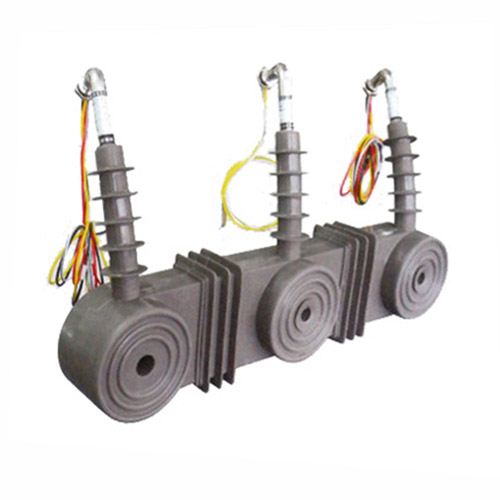
CT-10K 11kV Cast-Resin Current Transformer for Substation Metering and Protection – IEC 61869-2 Certified
Introduction to the CT-10K Current Transformer
The CT-10K is a high-reliability, cast-resin insulated current transformer designed for accurate current measurement and robust protection functions in medium-voltage power systems operating at 11kV (IEC standard) or 10kV (domestic Chinese grid equivalent). Engineered in strict compliance with IEC 61869-2 and GB/T 20840.2, this device leverages advanced vacuum pressure impregnation (VPI) epoxy resin technology to encapsulate its magnetic core and windings, ensuring long-term dielectric integrity even under harsh environmental conditions.
Operating Principle of Cast-Resin Insulation
Cast-resin insulation in the CT-10K utilizes a two-stage VPI process where the wound core assembly is first subjected to deep vacuum to remove moisture and air pockets, followed by pressurized impregnation with cycloaliphatic epoxy resin. This results in a monolithic, void-free structure with superior tracking resistance (CTI > 600), thermal class F (155°C) rating, and excellent mechanical strength. Unlike oil-filled alternatives, the solid dielectric eliminates fire hazards, leakage risks, and maintenance associated with fluid containment. The resin’s coefficient of thermal expansion closely matches that of copper and silicon steel, minimizing internal stresses during thermal cycling between -40°C and +40°C ambient temperatures. This design ensures stable performance over the transformer’s 25–30-year service life, even in coastal or industrial atmospheres with high humidity and pollution.
Advantages Over Oil-Immersed Designs
Compared to traditional oil-immersed current transformers, the CT-10K offers significant operational and safety benefits. Its dry-type construction eliminates flammability concerns, making it suitable for indoor substations, urban switchgear rooms, and confined spaces where fire codes restrict oil-filled equipment. The absence of oil also removes the need for periodic oil sampling, degassing, or tank inspections. Mechanically, the rigid epoxy housing provides superior resistance to vibration and seismic loads (tested per IEC 60068-2-6), critical in earthquake-prone regions. Electrically, the homogeneous dielectric reduces partial discharge activity to <5 pC at 1.2 × Ur (13.2 kV), well below the IEC 61869-2 limit of 20 pC. Additionally, the compact footprint—enabled by higher dielectric strength of epoxy versus oil-paper systems—facilitates retrofitting into existing 11kV panels without major civil modifications.
Typical Applications Overview
The CT-10K is engineered for dual-function deployment in both revenue metering and protective relaying circuits. In utility substations, it supplies scaled-down secondary currents (typically 1A or 5A) to kWh meters, demand recorders, and SCADA RTUs with accuracy classes up to 0.2S for billing-grade applications. Simultaneously, its protection-class windings (e.g., 5P20) deliver linear output during fault conditions up to 20× rated current, enabling precise operation of overcurrent, earth-fault, and differential relays. The unit is commonly installed on incomer feeders, transformer neutrals, capacitor banks, and motor control centers across industrial plants, renewable energy collector systems, and municipal distribution networks. Its IP54-rated terminal box ensures reliable secondary connections even in dusty or humid outdoor environments when mounted on pole-top or pad-mounted switchgear.
Technical Specifications
The CT-10K adheres to stringent dimensional, electrical, and thermal parameters defined by international and domestic standards. Below is a comprehensive specification table followed by detailed subsections.
| Parameter | Value |
|---|---|
| Rated System Voltage (Ur) | 11 kV (IEC) / 10 kV (GB) |
| Rated Insulation Level | 12/28/75 kV (Ur/LI/AC) |
| Primary Current (Ip) | 50 A to 4000 A (standard); custom up to 6300 A |
| Secondary Current (Is) | 1 A or 5 A |
| Current Ratio | Adjustable via multi-tap secondary (e.g., 400/1, 400/5) |
| Metering Accuracy Class | 0.2S, 0.5S (per IEC 61869-2) |
| Protection Accuracy Class | 5P10, 5P20, 10P10, 10P20 |
| Rated Output (Burden) | 2.5 VA to 30 VA (metering); 15 VA to 60 VA (protection) |
| Short-Time Thermal Current | 25 kA for 1 s (at 50 Hz) |
| Dynamic Withstand Current | 62.5 kA peak |
| Core Material | Grain-Oriented Electrical Steel (GOES), M4 grade |
| Insulation System | VPI cycloaliphatic epoxy resin, Class F (155°C) |
| Ambient Temperature Range | -40°C to +40°C |
| Altitude Limit | ≤ 1000 m (derating required above) |
| Humidity | Up to 95% RH non-condensing |
| Terminal Box Rating | IP54, brass terminals with anti-rotation screws |
Electrical Performance Parameters
The CT-10K’s electrical performance is defined by its composite error under specified burdens and current ranges. For metering class 0.2S, the composite error must not exceed ±0.2% at 20% to 120% of rated current with a cos φ = 1.0 burden. At 1% of rated current, the error limit relaxes to ±0.75%, enabling accurate low-load billing—a critical requirement for modern smart grids. Protection classes like 5P20 guarantee that the ratio error remains ≤ ±5% and phase displacement ≤ ±60 minutes at 20× rated current with the specified burden. The transformer’s knee-point voltage (Vk) exceeds 200 V for 5P20 cores, ensuring sufficient saturation margin during external faults. Rated outputs are precisely matched to connected devices; for example, a 15 VA protection winding driving a numerical relay with 0.5 Ω input impedance operates well within thermal limits even during prolonged overloads.
Environmental and Mechanical Ratings
Designed for global deployment, the CT-10K meets IEC 60060-1 insulation coordination requirements with a lightning impulse withstand voltage (LIWV) of 75 kV peak and power frequency withstand voltage (PFWD) of 28 kV rms for 1 minute. The cast-resin housing resists UV degradation, salt fog (per IEC 60068-2-11), and fungal growth, making it suitable for coastal and tropical installations. Mounting options include horizontal or vertical busbar through-hole configurations with standard M12 or M16 bolt patterns. The unit weighs approximately 28 kg (for 600/5 ratio), facilitating manual handling during installation. Seismic qualification includes horizontal acceleration of 0.3g (Zone 3 per IEEE 693), validated through shake-table testing. All external surfaces undergo hydrophobic treatment to prevent water film formation, reducing surface leakage currents in high-humidity conditions.
Typical Applications
The CT-10K serves as a foundational sensing element across diverse power infrastructure segments, delivering precision and reliability where measurement integrity directly impacts operational safety and revenue accuracy.
Substation Secondary Metering
In 11kV/0.4kV distribution substations, the CT-10K provides inputs to Class 0.2S revenue meters for commercial and industrial consumers. Its low-phase-displacement error (< ±10 minutes at 100% In) ensures minimal reactive energy measurement deviation, critical for power factor billing. When integrated with AMI (Advanced Metering Infrastructure) systems, the CT’s stable ratio over temperature (-40°C to +40°C variation induces <0.1% ratio drift) supports accurate time-of-use tariffing. For example, in a 20 MVA urban substation feeding a shopping mall, dual-ratio CT-10K units (e.g., 1200/5 for normal load, 200/5 for standby generator sync) enable seamless transition between grid and backup sources without meter recalibration.
On-Site Testing Procedures
Post-installation verification ensures the CT-10K performs within specifications under actual system conditions. All tests follow IEC 60044-1 and IEEE C57.13 methodologies.
Insulation Resistance Test
Using a 2500 V DC megohmmeter, measure insulation resistance between primary conductor and secondary windings/core, and between secondary windings and earth. Acceptance criteria: >1000 MΩ at 20°C. Correct for temperature using RT2 = RT1 × 2(T1-T2)/10. Low readings (<100 MΩ) indicate moisture ingress or resin cracking, requiring drying or replacement. Perform before and after cleaning terminal boxes to assess contamination impact.
Turns Ratio Test
Apply a low-voltage AC source (5–10 V) to the secondary winding and measure induced primary voltage. Calculate ratio as Vs/Vp. Compare to nameplate; tolerance is ±0.2% for 0.2S class, ±1% for 5P20. Use a dedicated turns ratio tester (e.g., Omicron CT Analyzer) for automatic comparison. Deviations >2% suggest inter-turn shorts or incorrect tap selection.
Polarity Test
Verify reducing polarity per IEC 61869-2 Figure 3. Connect a 1.5 V battery momentarily between P1 and P2. Observe secondary voltage spike on an oscilloscope or analog voltmeter: positive deflection at S1 confirms correct polarity. Incorrect polarity causes 180° phase shift, leading to relay misoperation or meter reversal. Document results with timestamped waveform captures.
Power Frequency Withstand Voltage Test
Apply 28 kV rms (50 Hz) for 1 minute between primary and grounded secondary/core. Use a calibrated test transformer with overcurrent trip (≤100 mA). No flashover or sustained discharge indicates pass. Reduce voltage gradually post-test to avoid transient overvoltages. Conduct only if factory test records are unavailable or after major maintenance.
Excitation (Saturation) Characteristic Test
For protection-class verification, plot excitation curve by applying increasing AC voltage to secondary and measuring current. Identify knee-point voltage (Vk) where slope changes sharply. For 5P20, Vk must exceed 200 V. Low Vk indicates core saturation risk during faults. Compare to factory curves; >10% deviation warrants core inspection for mechanical damage.
Preventive Maintenance Guide
Although cast-resin CTs require minimal maintenance, scheduled checks extend service life and prevent unexpected failures.
Periodic Inspection Protocol
Annual visual inspections should verify: (1) no cracks or tracking on resin surface, (2) secure terminal connections (torque: 2.5 N·m for M6 screws), (3) clean, dry terminal box with intact gaskets, and (4) proper grounding of core and housing (<0.1 Ω resistance). Use UV cameras to detect corona in dusk conditions. Record infrared thermograms during peak load; hotspots >10°C above ambient suggest loose connections. Clean housing with non-abrasive detergent; avoid solvents that degrade epoxy.
Maintenance Intervals and Fault Diagnosis
Every 5 years, perform insulation resistance and ratio tests regardless of visual condition. After system faults exceeding 10× In, conduct excitation tests to check for core remanence. Common failure modes include: (1) secondary open-circuit during operation—causes dangerous overvoltage (>2 kV)—always short secondary before disconnecting meters; (2) moisture ingress through damaged gaskets—evidenced by fogging inside terminal box; (3) core lamination damage from mechanical shock—detected via elevated excitation current. Replace units showing >20% ratio drift or insulation resistance <500 MΩ after drying.
| Interval | Action | Acceptance Criteria |
|---|---|---|
| Annually | Visual + IR scan | No cracks, ΔT < 10°C |
| Every 5 years | Insulation resistance + ratio test | >1000 MΩ, ratio error within class |
| After major fault | Excitation test | Vk within 10% of baseline |
| After 15 years | Partial discharge scan | <10 pC at 1.2× Ur |
Conclusion
The CT-10K 11kV cast-resin current transformer represents a benchmark in medium-voltage instrumentation, combining the dielectric reliability of VPI epoxy resin with the magnetic precision of GOES cores. Its dual compliance with IEC 61869-2 and GB/T 20840.2 ensures global applicability, while its robust mechanical design withstands extreme environmental and electrical stresses. Key technical advantages include ultra-low partial discharge (<5 pC), stable accuracy across temperature extremes (-40°C to +40°C), and immunity to fire hazards inherent in oil-filled alternatives. Field-proven in applications ranging from urban substations to offshore wind farms, the CT-10K delivers consistent performance for metering (0.2S class) and protection (5P20) over a projected service life of 25–30 years. Its maintenance-free operation, compact form factor, and rigorous type testing make it an optimal choice for modernizing aging infrastructure or deploying new smart grid assets. By adhering to exacting international standards and incorporating real-world operational feedback, the CT-10K minimizes total cost of ownership while maximizing measurement integrity and system reliability.