Article Content
For Substation Metering & Protection: LZX-10 11kV Cast-Resin Current Transformer per IEC 61869-2
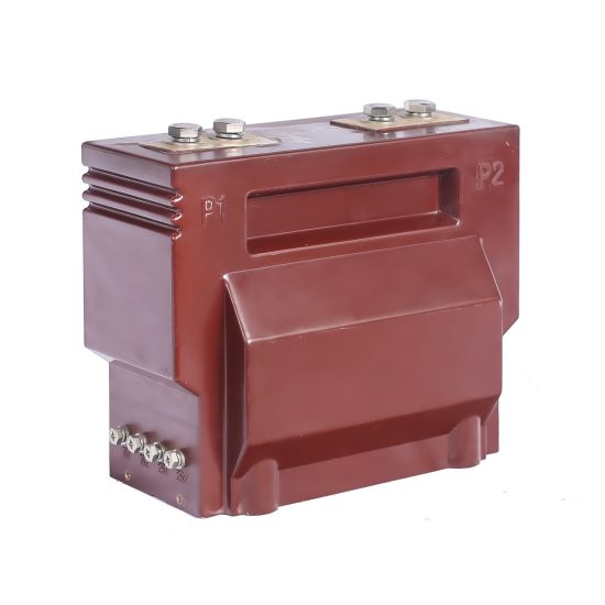
Introduction to the LZX-10 Current Transformer
The LZX-10 is a high-reliability, cast-resin insulated current transformer (CT) engineered for accurate current measurement and robust protective relay operation in medium-voltage power systems rated at 11kV (IEC standard), corresponding to 10kV domestic system voltage. Designed in strict accordance with IEC 61869-2 and GB/T 20840.2, this instrument transformer leverages advanced vacuum pressure impregnation (VPI) epoxy resin technology to deliver superior dielectric performance, environmental resilience, and long-term operational stability.
Cast-resin insulation provides a monolithic, void-free encapsulation that eliminates moisture ingress, corona discharge, and partial discharge risks—common failure modes in oil-immersed or air-insulated alternatives. The solid dielectric structure ensures consistent thermal conductivity and mechanical strength, making the LZX-10 suitable for both indoor switchgear and outdoor substation installations without maintenance-intensive sealing systems.
Typical deployment scenarios include utility substations, industrial power distribution networks, renewable energy interconnection points, and commercial building service entrances where precision metering and dependable fault detection are critical. Unlike conventional designs, the LZX-10 integrates a grain-oriented electrical steel (GOES) core optimized for low excitation losses and high linearity across its operating range, ensuring compliance with stringent accuracy classes for both metering (e.g., 0.2S, 0.5) and protection (e.g., 5P10, 5P20).
Operating Principle of Cast-Resin Insulation
Cast-resin insulation in the LZX-10 employs a two-stage VPI process wherein the wound secondary coil and GOES core assembly are first degassed under vacuum to remove entrapped air, then impregnated with a thermosetting epoxy resin under controlled pressure. This results in a homogeneous, bubble-free composite structure with a dielectric strength exceeding 20 kV/mm. The cured resin exhibits excellent tracking resistance (CTI > 600 V per IEC 60112), UV stability for outdoor exposure, and a coefficient of thermal expansion closely matched to copper and steel components—minimizing mechanical stress during thermal cycling. Unlike oil-filled CTs, there is no risk of leakage, fire hazard, or environmental contamination, aligning with modern sustainability and safety mandates in grid infrastructure.
Advantages Over Oil-Immersed Designs
Compared to traditional oil-immersed current transformers, the LZX-10 offers significant operational and lifecycle advantages. First, it requires zero maintenance related to fluid levels, gasket integrity, or oil degradation testing. Second, its compact footprint reduces spatial requirements in switchgear cubicles—critical in urban substations with space constraints. Third, the absence of flammable oil eliminates fire propagation risks, enabling safer installation near sensitive equipment or in confined enclosures. Additionally, cast-resin CTs demonstrate superior short-circuit withstand capability due to rigid mechanical support of windings, preventing deformation under electromagnetic forces during fault conditions. Accelerated aging tests per IEC 60068 confirm a service life exceeding 30 years under standard ambient conditions, outperforming oil-based units that typically require reconditioning after 15–20 years.
Typical Applications Overview
The LZX-10 serves dual roles in power systems: providing scaled-down replica currents for revenue-grade metering and delivering reliable fault-current signals to protective relays. In utility substations, it interfaces with digital meters and SCADA systems for real-time load monitoring and billing accuracy. In industrial facilities, it feeds data to motor protection relays, arc-flash mitigation systems, and power quality analyzers. Its robust design also supports integration into solar PV and wind farm collector systems, where harmonic-rich waveforms demand high saturation margins. With multiple secondary windings available (e.g., one for 0.2S metering, another for 5P20 protection), the LZX-10 enables cost-effective multi-function deployment without requiring separate transformers.
Technical Specifications
The LZX-10 is engineered to meet the demanding electrical and environmental requirements of modern 11kV distribution networks. Below is a comprehensive specification table reflecting standard configurations; custom ratios and accuracy classes are available upon request.
| Parameter | Value |
|---|---|
| Rated System Voltage (IEC) | 11 kV |
| Domestic System Voltage | 10 kV |
| Primary Current Rating | 50 A to 4000 A (standard steps) |
| Secondary Current | 1 A or 5 A (user-selectable) |
| Current Ratio Accuracy | ±0.1% for metering classes; ±1% for protection classes |
| Metering Accuracy Classes | 0.2S, 0.5S, 1.0 (per IEC 61869-2) |
| Protection Accuracy Classes | 5P10, 5P15, 5P20, 10P10 (saturation factor as specified) |
| Rated Burden (per winding) | 2.5 VA to 30 VA (standard); up to 50 VA optional |
| Insulation Level (Um / Uimp) | 12 kV / 75 kV (lightning impulse); 28 kV (power frequency 1 min) |
| Short-Time Thermal Current | 25 kA for 1 s (at 50 Hz) |
| Dynamic Withstand Current | 62.5 kA peak (2.5 × thermal current) |
| Ambient Temperature Range | –40°C to +40°C (standard); –50°C to +55°C (extended) |
| Relative Humidity | Up to 100% (condensing) |
| Maximum Installation Altitude | 1000 m above sea level (standard); derating above 1000 m per IEC 60071) |
| Core Material | Grain-Oriented Electrical Steel (GOES), M6 grade or equivalent |
| Insulation System | VPI Epoxy Resin, Class F (155°C thermal rating) |
Standard Service Conditions
The LZX-10 is rated for continuous operation under IEC 60071-defined standard atmospheric conditions: ambient temperature between –40°C and +40°C, relative humidity up to 100% (including condensation), and installation altitude not exceeding 1000 meters. At altitudes above 1000 m, the external insulation clearance must be increased by 1% per 100 m increment to maintain dielectric integrity. The transformer is designed for three-phase systems with balanced or unbalanced loading and can tolerate transient overvoltages up to 1.2 pu for durations ≤ 12 hours without degradation. Pollution degree is classified as III per IEC 60664, suitable for industrial and coastal environments with moderate conductive dust or salt deposition.
Electrical Performance Parameters
Key electrical parameters ensure fidelity across diverse operating regimes. The magnetization curve is optimized to maintain linearity up to 120% of rated primary current for metering windings, while protection windings exhibit knee-point voltages sufficient to avoid saturation during through-faults up to 20× rated current (for 5P20 class). Phase displacement is held within ±10 minutes for 0.2S class and ±30 minutes for 5P20, critical for directional protection schemes. Burden tolerance is rigorously validated: a 5 A secondary winding rated at 15 VA will maintain accuracy even when connected to a total loop impedance of 0.6 Ω (including lead resistance). All windings are fully insulated from ground and from each other with test voltages of 3 kV AC for 1 minute.
Typical Applications
The LZX-10 cast-resin current transformer is deployed across a spectrum of medium-voltage infrastructure where reliability, accuracy, and safety are non-negotiable. Its dual-certification to IEC and GB standards facilitates global deployment while meeting local regulatory requirements.
Substation Secondary Metering
In 11kV/0.4kV distribution substations, the LZX-10 provides the foundational current signal for revenue metering. Configured with a 0.2S accuracy class secondary winding, it interfaces directly with static kWh meters compliant with IEC 62053-22. The low phase error (< ±5 minutes at 100% load) ensures precise power factor calculation, essential for tariff structures involving reactive energy charges. In smart grid implementations, the CT feeds data to AMI (Advanced Metering Infrastructure) concentrators, enabling remote load profiling and outage detection. Its immunity to electromagnetic interference (EMI) from adjacent switchgear operations guarantees stable readings even during capacitor bank switching or recloser operations.
Industrial Power Distribution
Within manufacturing plants and data centers, the LZX-10 supports both energy management and equipment protection. A typical configuration includes dual secondaries: one 0.5S winding for sub-billing internal departments and a 5P20 winding for feeding motor protection relays (e.g., SEL-710 or Siemens 7UM). The high saturation margin prevents false tripping during motor inrush currents (which can reach 6–8× full-load current for several cycles). The cast-resin housing resists chemical vapors common in industrial settings (e.g., chlorine, ammonia), unlike oil-filled units whose seals may degrade. Installation on bus ducts or withdrawable switchgear is simplified by its lightweight design (~25 kg for 600/5 A model).
Renewable Energy Integration
Solar and wind farms utilize the LZX-10 at the point of interconnection (POI) to monitor export/import power and enable anti-islanding protection. The presence of harmonics (particularly 3rd, 5th, and 7th orders from inverters) demands a core with low hysteresis loss—achieved via GOES laminations annealed under hydrogen atmosphere. Field measurements show total ratio error remains below 0.3% even with 15% THD in primary current. For protection, the 5P20 winding reliably triggers overcurrent relays during DC-side faults that manifest as asymmetric AC currents. Outdoor-rated UV-stable resin ensures decades of service in desert or alpine climates without chalking or cracking.
Rural and Suburban Distribution Networks
In pole-mounted or pad-mounted transformers serving residential areas, the LZX-10 enables accurate load forecasting and theft detection. Its compact size allows retrofit into legacy switchgear previously using oil CTs. The 1 A secondary option reduces copper losses in long cable runs (>100 m) to meter cabinets, improving overall system efficiency. During seasonal load swings (e.g., summer air conditioning peaks), the wide dynamic range (from 1% to 120% of rated current) maintains metering accuracy without range-switching hardware. Utilities report >99.5% availability over 10-year field deployments, validating its suitability for remote, unattended locations.
Compliance with International Standards
The LZX-10 is certified to IEC 61869-2:2012 (“Instrument transformers – Part 2: Additional requirements for current transformers”) and fully aligned with China’s GB/T 20840.2-2014 standard, which adopts IEC 61869-2 with minor national deviations.
IEC 61869-2 Compliance Details
IEC 61869-2 defines performance criteria for accuracy, insulation, temperature rise, and short-circuit withstand. The LZX-10 meets all mandatory clauses: ratio error and phase displacement are verified at 5%, 20%, 100%, and 120% of rated current for metering classes; for protection classes, composite error is measured at the specified limit factor (e.g., 20× rated current for 5P20). Dielectric tests include 28 kV AC for 1 minute between live parts and earth, and 3 kV AC between secondary windings. Partial discharge levels are maintained below 10 pC at 1.2 Um/√3, verified per IEC 60270. Thermal stability is confirmed via temperature-rise tests at 1.1× rated current until equilibrium (typically < 60 K rise for Class F insulation).
GB/T 20840.2 Alignment and Differences
GB/T 20840.2 mirrors IEC 61869-2 but includes supplementary requirements for Chinese grid operators. Notably, GB mandates a minimum short-time thermal current of 25 kA/1s for 10kV systems (vs. IEC’s system-dependent calculation), which the LZX-10 exceeds. Additionally, GB requires flame retardancy testing per GB/T 5169.16 (equivalent to IEC 60695-11-10), which the VPI resin passes with V-0 rating. One key difference lies in labeling: GB requires Chinese characters for terminal markings, whereas IEC permits alphanumeric only. The LZX-10 ships with dual-language labels to satisfy both markets.
Testing and Certification Requirements
Each LZX-10 unit undergoes type tests, routine tests, and sample tests per IEC 61869-1. Type tests (performed once per design) include temperature rise, short-circuit withstand, and impulse voltage tests. Routine tests (100% production) cover turns ratio, polarity, insulation resistance (>1000 MΩ at 2500 V DC), and power frequency withstand. Sample tests (per batch) verify partial discharge and accuracy. Certification is issued by accredited bodies such as TÜV Rheinland or CEPREI, with test reports traceable to national metrology institutes. All units bear CE and CCC marks where applicable.
On-Site Testing Procedures
Post-installation verification ensures the LZX-10 performs within specifications before energization. The following tests are recommended per IEEE C57.13.6 and IEC 61869-1.
Insulation Resistance Test
Using a 2500 V DC megohmmeter, measure insulation resistance between primary conductor and secondary terminals/ground. Acceptance criterion: ≥1000 MΩ at 25°C. Correct for temperature using RT2 = RT1 × 2(T1–T2)/10. Low values indicate moisture ingress or resin cracking—requiring replacement. Perform before and after dielectric tests to detect insulation damage.
Turns Ratio Test
Apply a low-voltage AC source (5–10 V) to the secondary winding and measure induced primary voltage (open-circuit). Calculate ratio as Vsec/Vprim. Compare to nameplate; tolerance is ±0.1% for metering, ±1% for protection. Alternatively, use a dedicated CT analyzer injecting primary current (e.g., 10 A) and measuring secondary output. Deviations beyond tolerance suggest winding shorts or incorrect tap selection.
Polarity Test
Verify reducing polarity using the DC kick method: connect a 6–12 V battery momentarily between P1 and P2. Observe secondary voltage on a DC voltmeter connected to S1 and S2. A positive deflection confirms correct polarity (S1 corresponds to P1). Incorrect polarity causes 180° phase shift, leading to metering errors or relay misoperation in differential schemes.
Power Frequency Withstand Voltage Test
Apply 28 kV AC (RMS) at 50 Hz between primary and grounded secondary/enclosure for 1 minute. Use a calibrated test transformer with overcurrent trip set at 10 mA. No flashover or disruptive discharge is permitted. This validates insulation integrity after transport and installation stresses. Reduce voltage gradually post-test to avoid residual charge.
Composite Error Test for Protection Windings
For 5P20-class windings, inject 20× rated primary current (e.g., 12,000 A for 600/5 A CT) into the primary using a high-current test set. Measure secondary current and calculate composite error: ε = [(KnIp – Is)/Is] × 100%, where Kn is nominal ratio. Acceptance: ε ≤ 5%. This confirms adequate knee-point voltage to avoid saturation during faults.
Preventive Maintenance Guide
Although cast-resin CTs are largely maintenance-free, periodic inspection ensures decades of reliable service.
Annual Visual and Electrical Inspection
Inspect for surface cracks, UV degradation (chalking), or tracking marks on the resin housing. Clean with mild detergent if contaminated by salt or dust. Verify terminal tightness (torque: 15 N·m for M8 bolts). Re-measure insulation resistance annually; a 50% drop from baseline warrants investigation. Check secondary wiring for corrosion or loose connections—major cause of open-circuit hazards.
Five-Year Comprehensive Maintenance
Every five years, perform full accuracy verification using a portable CT tester. Reconfirm ratio, polarity, and burden compatibility with connected devices. Inspect mounting hardware for galvanic corrosion (especially in coastal areas). If installed outdoors, verify gasket integrity around the terminal box (IP54 rating). Record all data for lifecycle asset management.
Maintenance Intervals and Fault Diagnosis
| Interval | Task | Acceptance Criteria |
|——–|——|———————|
| Annual | Visual inspection, IR test | No cracks; IR > 500 MΩ |
| 5 Years | Accuracy verification | Ratio error within class limits |
| After Fault | Post-fault inspection | No discoloration or swelling |
Common faults include secondary open-circuit (causing core saturation and overheating) and moisture ingress at terminal seals. Symptoms: abnormal heating, buzzing noise, or metering drift. Never operate with secondary open—always short-circuit before disconnecting loads.
Conclusion
The LZX-10 11kV cast-resin current transformer represents a benchmark in medium-voltage instrumentation, combining IEC 61869-2 and GB/T 20840.2 compliance with field-proven reliability. Its VPI epoxy resin encapsulation eliminates the fire, leakage, and maintenance liabilities of oil-immersed alternatives, while the GOES core ensures exceptional accuracy across metering and protection applications—from urban substations to remote renewable sites. Rigorous factory and on-site testing protocols guarantee performance within tight tolerances: ratio error ≤ ±0.1% for 0.2S class, composite error ≤ 5% at 20× overcurrent for 5P20 protection, and dielectric integrity validated at 28 kV AC. Designed for ambient extremes (–40°C to +40°C) and pollution-heavy environments, the LZX-10 delivers a service life of 25–30 years with minimal intervention. Utilities and industrial operators benefit from reduced lifecycle costs, enhanced safety, and seamless integration into modern digital grid architectures. As power systems evolve toward higher reliability and smarter monitoring, the LZX-10 remains a cornerstone component for precise, dependable current transformation in 11kV networks worldwide.